An H-bridge circuit typically provides motor control in robotic designs. Low voltage, low amperage control signals (TTL) are used to control motors. The H-Bridge can interpret these signals into a Motor Go Forward, Motor Go Backward, Motor Stop commands. Often speed can be implemented using PWM (Pulse-width modulation) through a H-Bridge. H-Bridges are extremely important in robotics. It is like the connection between the brains and the muscle of a robot. The brains being a computer or micro-Processor, and the muscles being a motor. This Matrix (when it is somewhat completed) should help you step through the process of selecting an appropriate H-Bridge design for your application.
Terms
Ampere - (symbol A) the unit of measure for electrical current
Inductance - The magnetic field that is generated when a current is passed through an inductor, typically a wire coil. Important, because a motor which is spinning is also a generator. The current generated from this can (and has) put many H-bridges in Magic Smoke mode.
Load - the work a motor is doing
No-load - is the speed and current drawn by a motor when there is no external load
Stalled - is the current and torque of a motor when so much load is put on the shaft, the motor does not turn
Rated - maximum load conditions which the motor can be operated continuously
Magic Smoke - (slang) the smoke released from your circuit, which previously made it work. When a circuit becomes overloaded and components burn, they make magic smoke.
MOSFET - a silicon switch which is capable of switching a considerable amount of current, typically more than BJTs. Due to the fact that MOSFETs conduct less when heated, they can be ganged together to provide massive current capability. BJTs in contrast conduct more when they get hot, and will destroy themselves in similar conditions.
Ohm - a unit of measure for electrical resitance
Ohm's law - a helpful formula for figuring out how much work your circuit can do, before going into "Magic Smoke" mode. I = V/R. Current = Voltage / Resistance
Shoot Through - a term describing when some of the switches in an h-bridge do not open or close at the appropriate time. Shoot through shorts the power and can lead to circuit destruction. It is a good thing to avoid when possible. Some h-bridges are designed to prevent shoot through, other designs leave it to control circuitry.
Short - a term describing power from a circuit going directly to ground without resistance. Another good thing to avoid. It can destroy batteries, circuits, and the wire or trace which was shorted.
Volt- (symbol V) the unit of measure for electrical potential/pressure
Sign Magnitude - a method of using 2 inputs to an h-bridge, in which one input signals direction, and a PWM input gives the magnitude of drive.
Locked Antiphase - input method where direction and magnitude are a single PWM input. At 50% duty the motor is stopped, lowering the duty percent would increase drive one direction, raising the duty cycle would increase in the opposite direction. Offers true 4 quadrant control of motors (CW driven, CW regenerating, CCW driven, CCW regenerating), but increases switching which increases heat.
How it works
How to select the appropriate H-Bridge design
Measure resistance of the coil of your motor To find the stall current of your motor use Ohm's Law V/R=I (Current = Voltage/Resistance). For example if you measure the resistance of a motors leads at 2.4 Ohms and your battery is 24 volts, your stall current will be : 24 volts / 2.4 Ohms = 10 Amps. So if your motor stalls, your circuit should be protected or capable of handling 10 amps.
BOA's Brilliant Hybrid H Bridge
BOA's Brilliant Hybrid H Bridge
Description
BaseOverApex's design of a great Hybrid H-bridge. The hybrid is a combination of relays and MOSFETs. The relays are for forward and reverse switching. The MOSFETS can accept a high frequency PWM for speed control. This design has been built (not just theory) and is currently powering one of BOA's great bots. Hopefully he will post a version of the PCB art - although it might be good to rework it so that the PIC is not part of the design, as others might be using different methods of control.
Schematic is completely wrong at the moment - will fix
Max PWM Frequency
Features
forward, reverse, pwm speed control, current overload protection, fuse
Parts List
Schematic
BreadBoard
Gerber
BOA’s Brilliant Hybrid H Bridge - Robologist Mod
BOA’s Brilliant Hybrid H Bridge - Robologist Mod
Description
BaseOverApex’s design of a great Hybrid H-bridge. The hybrid is a combination of relays and MOSFETs. The relays are for forward and reverse switching. The MOSFETS can accept a high frequency PWM for speed control. This design has been built (not just theory) and is currently powering one of BOA’s great bots. Hopefully he will post a version of the PCB art - although it might be good to rework it so that the PIC is not part of the design, as others might be using different methods of control.
Very small number of components, includes a under current protection line, will not “shoot through”
Cons
Schematic is completely wrong at the moment - will fix
Max PWM Frequency
Features
forward, reverse, pwm speed control, current overload protection
Parts List
Schematic
BreadBoard
Gerber
SIMPLE LOW POWER NPN PNP H-Bridge
SIMPLE LOW POWER NPN PNP H-Bridge
Description
Design which contains a very small amount of components for a very small capacity H-Bridge. The NPN transistors can be substituted with a variety of differently rated components. 2N2222 TIP120, etc.
Dependent on the transistor used - 2n2222 can sink ~800 mA, a TIP 120 can drive 5 amps with proper heat sink
Max Voltage
50 Volts
Build Time
Pros
small, inexpensive
Cons
no protection of shoot through, will only drive small motors
Max PWM Frequency
Features
forward, reverse, pwm speed control
Parts List
Schematic
BreadBoard
Gerber
SINGLE CHIP CONTOLLERS
SINGLE CHIP CONTOLLERS
Description
Design which contains a very small amount of components for a very small capacity H-Bridge. The NPN transistors can be substituted with a variety of differently rated components. 2N2222 TIP120, etc.
Krumlink - It is being implemented in my revised AREV-RSPF232
Max Current
1.2 Amps per line
Max Voltage
4.5 VDC to 40 volts (Forgot max but it is around 40 VDC) for motor lines / VCC2
Build Time
Pros
single chip, no external peripheral stuff needed, just hook up the motors, input and enable lines and you are good.
Cons
The SN754410 does not have build in clamp diodes, so you need to add them. The internal diodes are for ESD protection Pulldown resistors may be wanted to prevent the enable lines drifting high Low max voltage for motors but with internal diodes it drops the voltage to 3.1VDC anyways.
Max PWM Frequency
Features
Simple to hook up, you do not need PWM and it is easy to throw together and use with LED’s too
No shoot through protections, uses 4 inputs, untested
Could be improved by connecting upper and lower inputs, then adding an inverter attached between right and left sides for lock antiphase single input drive. Test shoot-through with uppers/lowers connected for feasibility.
Max PWM Frequency
Features
forward, reverse, pwm speed control
Parts List
Desig  Qty  Part#             Each  Total    Dist      Description
*U1,U2  2   579-TC4427ACPA    $1.36 $2.72   Mouser    Microchip TC4427CPA 1.5A MOSFET driver
*Q1,Q2  2   726-SPP80P06P     $3.02 $6.04   Mouser    Infineon SPP80P06N P-ch 60V 80A FET TO-220
*Q3,Q4  2   726-IPB080N06NG   $2.11 $4.22   Mouser    Infineon IPB080N06N G N-ch 60V 80A FET TO-220
*C1     1   647-UVY1E221MED1TA 0.11  0.11   Mouser    Nichon 220 uF 25 v Electrolytic Cap
*total $13.09
Excellent - thanks Krumlink, there is so much diverse information out there, it would be awesome to refine it and make it accessable for everyone. Can you edit the component page directly vs. putting in a comment. One of the reasons I put it in the component area was the idea that many of the users would edit it directly. Comments are great, but it takes digging to get the info out. Also I don’t believe I got an email notification when you put a comment in, I wonder if this is a “feature” of Components?
As we have discussed before As we have discussed before in other threads, the SN754410 does not have build in clamp diodes, so you need to add them. The internal diodes are for ESD protection
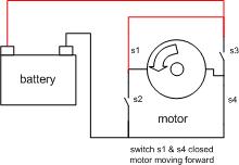
Nice piece. In your animation, though, when S3 and S4 (or, of course, S1 and S2 or all four) are closed, it’s not the motor that goes “phut” it’s the power supply, battery, fuses, FETs. I’ll work on a schematic for my hybrid with flyback diodes, inverting transistors (fail safe mode) and no PIC. I’ll do Eagle PCB artwork, too.
I will GIVE a board FREE to anyone who creates a custom LMR one-chip I2C driver for it using only a low pin-count (preferably dip 8) PIC. Here’s the spec:
3 data registers will be made available by the I2C slave:
PWM ratio register affording up to 127 speeds in each direction over a range of -128 to +127. The device will offer at least 8 different speeds in each direction over this range. 0 is “off”.
Ramp time register, allowing the speed to ramp up /down, 0 being instantaneous, 255 being an arbitrary period of maybe 60 seconds.
The driver will suport two channels, so there will be two of each of the above.
Connections to the chip will be 2 outputs (one for each direction relay) 2 outputs (one for each PWM FET) and two DIOs (I2C clock and data lines).
it’s a piece in progress - Drupal does not have revision control, wiki does. Drupal was not really made for many authors to edit a single document, wiki is. All it is telling you is I put a picture marker there, but currently have not put the picture… I have to create it first, or if you have one you could upload it, but you have to be logged in first. Anyone can upload if they create an account first. You just have to press “create an account” first.
Thanks, Appreciate the input, Unlike the grammer & 2-compliment mistake, I did actually know that. I’ve expierenced it too many times not too… The animation was an after thought @ 1:00 am in the morning, so I kind of rushed it. I’m going to re-do it and show all the possible issues, for example what the current and voltage look like when the motor suddenly stops, and that can put your switches into 1 time smoke mode, or the motor stalling, which can put the motor into 1 time smoke mode… etc. instead i put a “place holder” until I come back with the details. (the animation created different sizes too -> more fixing)
So much more stuff, opto-couplers, electrical isolation, circuit protection, underload sensing, dang I wish I had all this info when I began ! But now I get to share with others, how NOT to do my stupid mistakes…
I take it the challenging part of your challeng is the 8 pin PIC programming vs circuit design? For example I often make 555 PWM circuits, and this could be sent to the PIC (forgive my ignorance, I’m PIC challenged) … but you want all that functionality coming from the PIC. Why haven’t you done it? I have always gotten the impression you are the Master of low level PIC programming. I would be interested in giving it a try but it might take me years (not that that would stop me). I have a feeling that Master-San BOA can pull this one out of his sleeve in minutes?
Regardless, I would be interested in taking the challenge - I’m always interested in exploring/burning new circuitry.
BTW - your circuit was rendered by me completely wrong, maybe I should have waited before posting this … it is probably rev 0.66 . But, I’ll update that later too. So much to do … so little time.
a noobish question: if the motor stalls (=doesn’t move) why does the circuit have to be protected from, say, 10 amps (if my stall current is 10 amps)? I mean… current differently from voltage, doesn’t get “absorbed” by components, so you would anyway have the same current going around your circuit, but is this true?
In other words: what is the difference if i have a stalled motor in my circuit rather than having a motor working properly.
Nice walkthrough btw. I think have to get inspired from these kind of pages, they gather informations in one single place, and this is veeery useful. Good job.
wouldn’t you immediately fry the mosfets as soon as you stopped with a motor which takes 80 amps without protection diodes? The protection diodes seem always to have a smoke no smoke difference in my designs. I’m guessing it has to do with the motors I’m using - rather large…
Also - shouldn’t the Gate voltage for the P-channels be higher than the Source? My mofsets heat up if that does not happen, and I think its why the LM1602 boost pin, so it can pump the voltage above the Source - or Drain if your dealing with Top N-Channel mosfets.
Brushed DC motors draw less current the faster they go. At stall they draw the most current possible, and have the highest torque, at “free run” they have the highest speed while drawing the least amount of current. And it is typically a linear relationship.
If you have a motor that draws 500 mA just running on it’s own, nothing holding the shaft, it is possible for that same motor to pull 5 or 10 A when the shaft is locked down. Likewise a 3 A draw on a free spin, might turn into 30 A locked. You set up your motor driver to handle the worst case, stall. Which every motor starts out from, since they start from rest.
It might, but most FETs have body diodes that can help quite a bit. The FETs themselves rate at 80 A contiinuous, and depending on the switching method, it might actually handle it. Forgot to mention that the probable limiting factor would be the ability to get heat off the devices, by heat sink, and fan. I’d have to check over the thermal qualities of the device to see what it would take.
P-channels are switched by bring the gate negative in reation to the source, by about the same 10 or 12 volts you’d normally switch N-channels up from. So the TC4427 when switched high on the P driving input, would be switching it up to the 12 volt source and shutting it off. When the input is switching low, it would bring the gate to ground and turn the P-channel on since it is 12 volts lower than the positive source. So you could tie both inputs of a sides gate drivers together to operate that side. But I’d left them seperate so that the operating micro could be programmed to set up a dead time between the upper and lower to prevent shoot through if needed.