

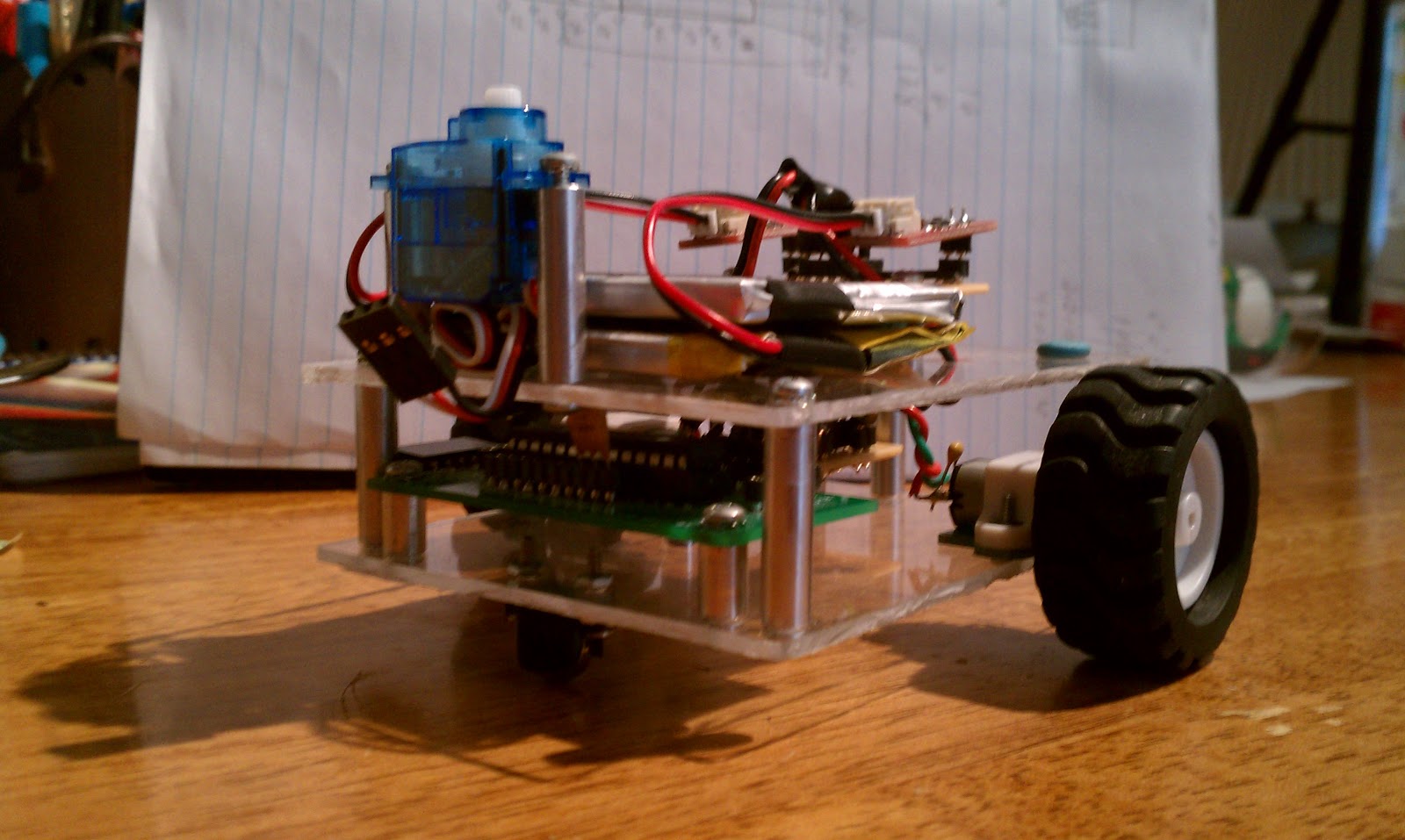
Hello LMR! I've been away for far too long. Here is my latest robot attempt. He hasn't told me his name yet. For now, I'm calling him FlexiPlexi. His base is really acryllic, but Plexi rhymes better. I call him Flexi because he has a number of small modules that can be moved around and reused. Also, I plan on three bases for him with 3 distinct missions. The first will be like the basic LMR SHR, exploring with a Sharp IR sensor on a micro servo "neck". The next incarnation will swap out the servo and IR for a line follower array. Then, the 3rd iteration will mount a number of forward and side looking IR sensors and bump sensors. The goal for the 3rd version is a complete micromouse.
The first version will use PWM control on the motors. It will work on wheel alignment, straight motion, exploration, and wall following. It will then incorporate the wheel encoders to learn odometry. The 3rd iteration will depend on this. So far, It has the bases cut out, the motor driver board created, a carrier board created, and the power array created. Some motor test code has proven the PWM routines. There is an ugly daughter board looming in the future to connect the micro servo and Sharp sensor to power and the PIC.
Here are some pictures:
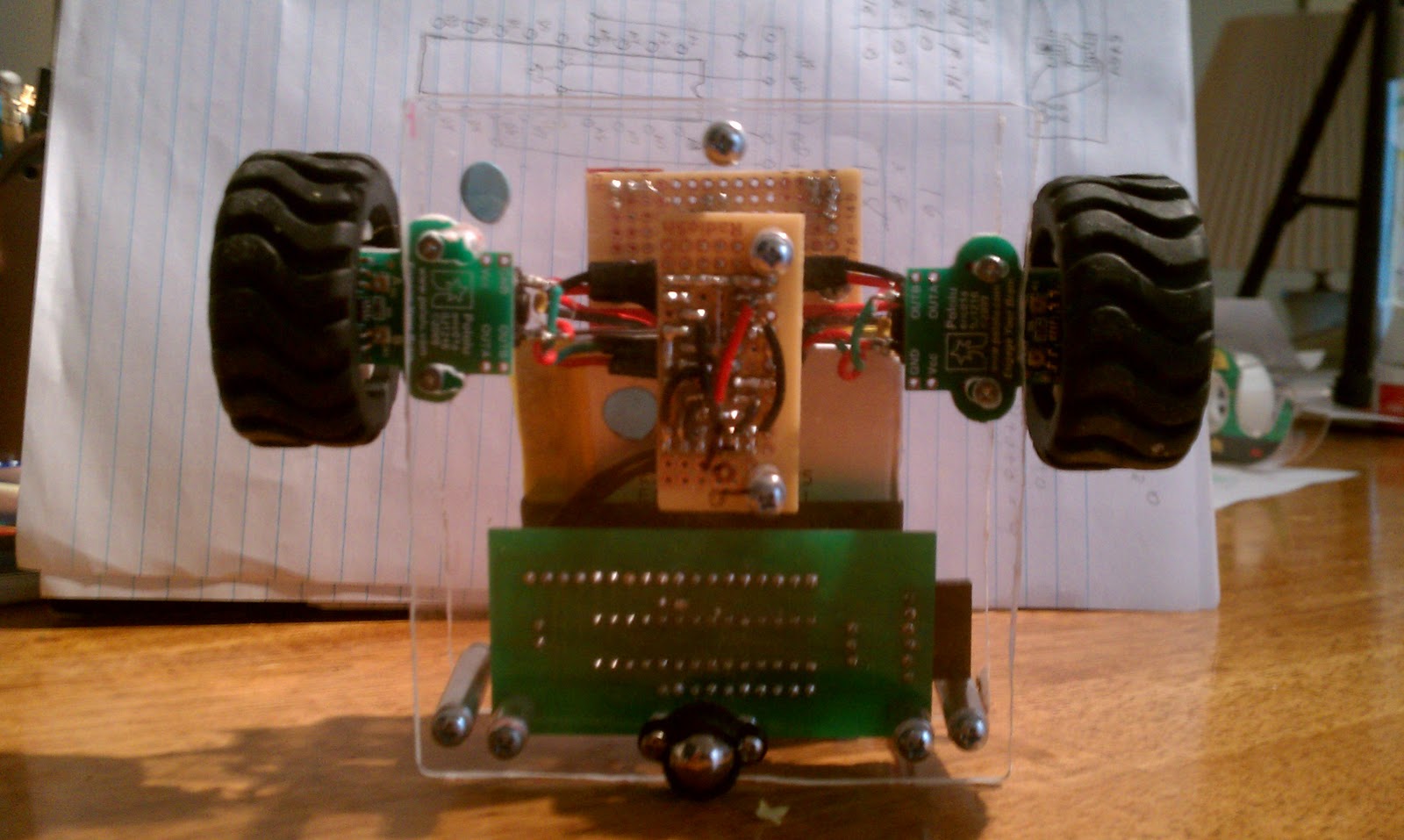
From the back:
From the Top:
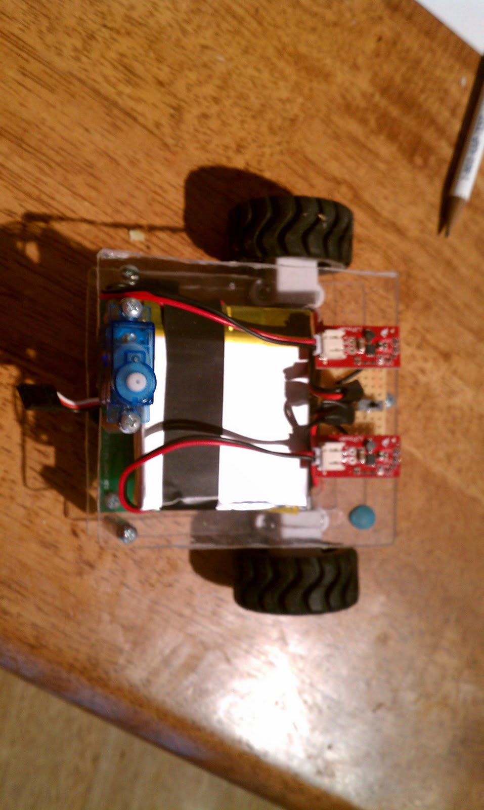
From the Bottom:
Top of the Lower Board:
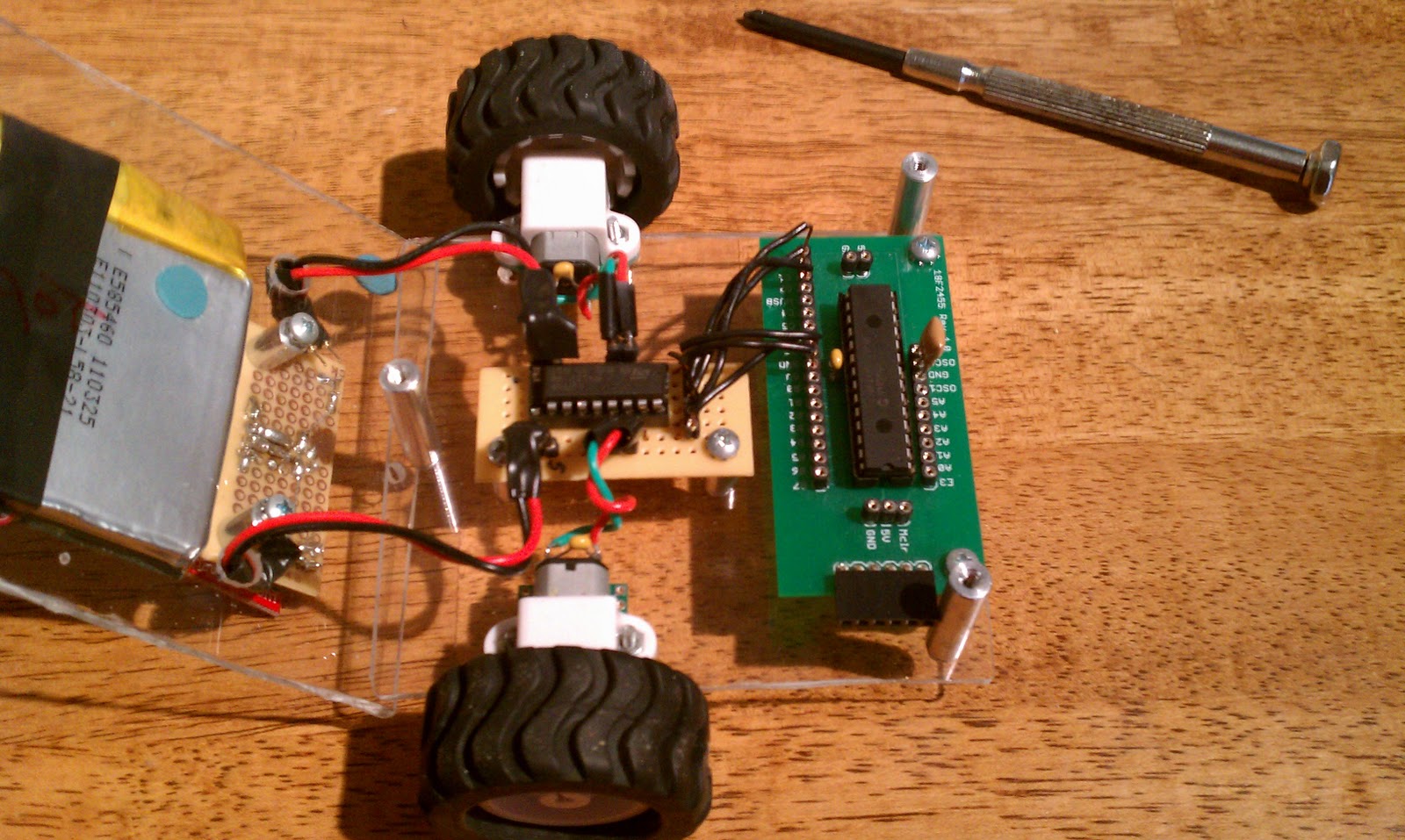
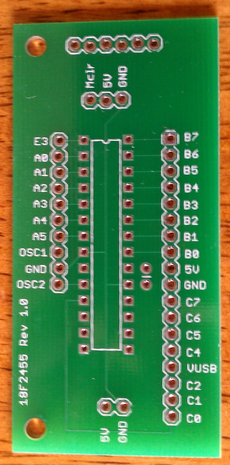
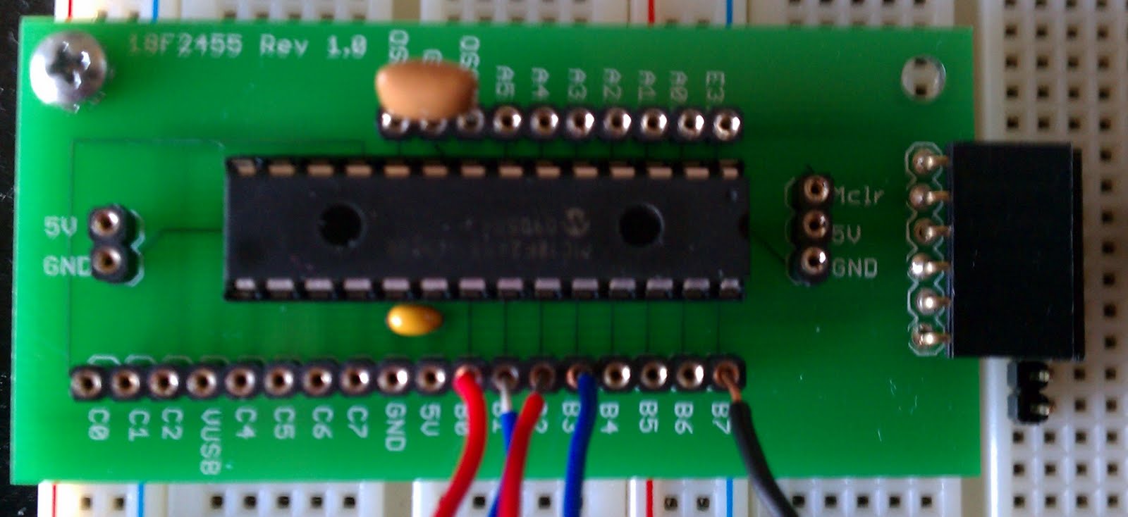
Notice the green board? This is a carrier board for the 28 pin PIC. I designed this in Eagle and had it made over at BatchPCB. It took a good month or so to arrive, but it was cheap!. It has an ICSP header. The resonator has pins, so various clocks can be used. There are power inputs on each end and in the middle of the long row of pins. Here are some close-ups:
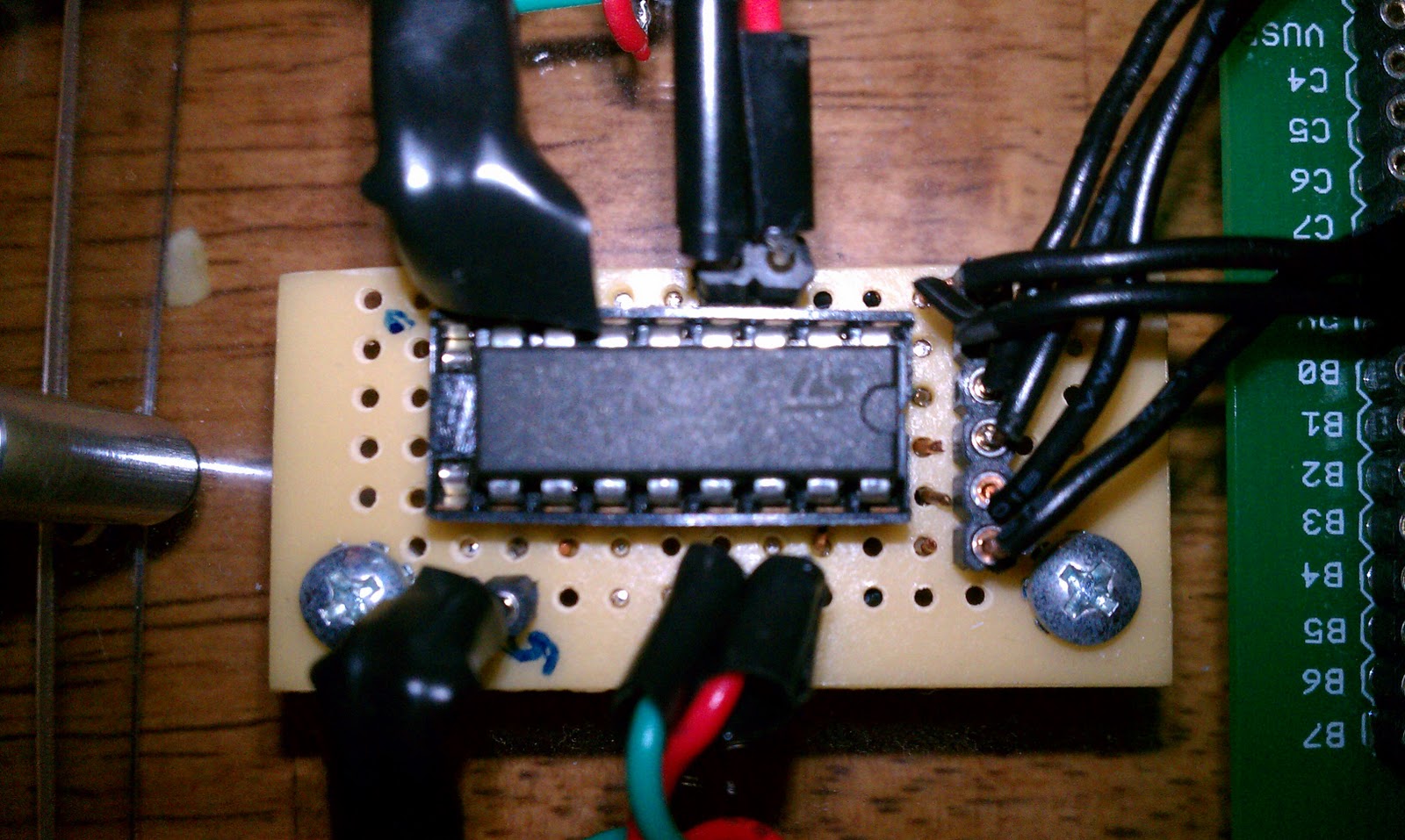
Here is my home made motor driver board:
Most of the design was inspired by Patrick McCabe's mouse. I liked the modular design and the acryllic base. I also like the carrier board he uses for the AVR. I couldn't find anything like it for PIC, so I made my own.
The bad part of this design is the power ( as well as all the electrical tape ). I know I'll get lots of feedback on that from observant LMRtians. I'm using 2 3.7V LiPo batteries. Each feeds into a 5V booster circuit. One powers the motors, the other everything else. Here is the problem. I have nothing in place to protect the circuit other than what might be in the motor driver chip. In particular, I'm worried about stall torque. Each motor has a stall torque of 500 mA at 6V. The boost converter can source at most 600 mA. I know I need some switch diodes and a cap. Can anyone help me with a design and values? Everything is boosted to run at 5V.
That's all for now. Look forward to your comments and suggestions!
Modular Robot - different bases will allow explorer, line follower, micromouse
- Actuators / output devices: one mini servo, 1:30 ration Pololu micro metal gear motors
- Control method: autonomous
- CPU: Pic 18F2455
- Operating system: OpenSuse Linux
- Power source: 2 - 3.7V LiPo batteries ( 1000 maH each ) with 5V boost converters
- Programming language: Assembler
- Sensors / input devices: Various IR, depending on form
- Target environment: indoor, smooth flat surfaces
This is a companion discussion topic for the original entry at https://community.robotshop.com/robots/show/flexiplexi