

I'm currently a sophomore at Worcester Polytechnic Institute studying Robotics Engineering. The third course in the series, RBE 2002, focusing on sensors. In a group of 4 students, we built a robot that could autonomously navigate a maze, locate a flame, put it out and report its X,Y, and Z position relative to its starting position. The robot was required to use an IMU and a flame sensor provided to us. All other sensors and parts are up to the group to use to complete the challenge. To measure displacement we used the encoders to calculate distance once we detected a wall. We then used the gyro data to figure out what the sign of the vector was. We then added either the X or Y compent to its respective array. When we detected the flame, we rotated the robot so it could find the distance from the flame to the robot, added that vector. Then we summed it all and did some simple triq to find the exact hyptonese of the flame relatative to the origin.


Vector Additon for tracking location
The course’s final project was to design, construct and program a robot that is “capable of navigating a structured environment, finding and extinguishing the simulated fire (a candle) and report the location of the fire in reference to where the robot started” (Putnam). The team conducted research, brainstormed and did analysis before coming up with a final design. The group begin by breaking up the entire project into subproblems to make it easier to work on. The divisions were physical design of the robot, detecting the flame, navigation of course, and position of flame. Each of these divisions had a subset of problems. The physical design of the robot needed to be able to fit within a 12.5” cube, extinguish a flame and needed some means to indicate the location of the flame. The system responsible for detecting the flame needed to be able to scan a range from 10 cm to 30 cm and had to be within a distance that the flame sensor can accurately detect flame or no flame. Navigation of the course and position of the flame had many sub-problems. The robot needed a way to accurately track displacements as it traversed the course, determine the vector heading, follow the walls and avoid obstacles. Once the team established the specific requirements and determined the subproblems, research was conducted.
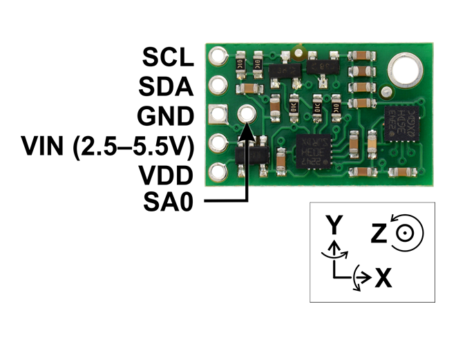
Pololu's MinIMU-9 v3 board
An Inertial Measurement Unit (IMU) is an electronic circuit that combines multiple sensors to collect angular velocity, linear acceleration and sometimes compass headings. The MinIMU-9 circuit, which can be seen in figure 1, provided by Pololu, contains a 3 axis gyro, 3 axis accelerometer and a 3 axis magnetometer. A gyroscope measures the angular momentum which needs to be tracked over time in order to get the current angle. This sensor tends to drift while tracking the angle, which can make it difficult to get reliable information. The error in the MEMS gyro is “perturbed by some thermo-mechanical noise which fluctuates at a rate much greater than the sampling rate of the sensor” (Woodman). Due to the cheap cost of the sensor and factors outside of the groups’ control, the sensor sometimes reports inaccurate readings. However, the gyroscope is good at measuring sudden movements. The accelerometer measures both static and dynamic accelerations (Woodman). The sensor can be noisy, but it does not need to be tracked, so drift is not an issue. Accelerometers are useful for tracking angles over a long period of time. The magnetometer is a microelectromechanical or MEMs device. To deal with this inaccurices, we implemented a complimentary filter. http://www.pieter-jan.com/node/11. This filter, takes a weighted average between the gyroscope and the acceleromter and after messing around with it, took care of our drift issues very well. An issue arose by using the complimentary filter. The software needed to run every 10ms and we tried running that code on Interupt service routine (ISR), but it was taking too long to execute the code in the ISR. To fix this we had a seperate arduino uno whos sole purpose was to run the comp filter and read the IMU. When the mega needed odemetry data it would make an request over serial to the UNO.
![]()
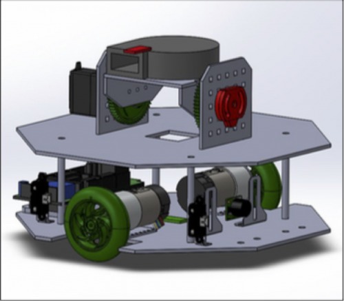
CAD Model of robot
The robot would have two levels, a lower level and an upper level. The lower level will hold the Arduino Mega, drive motors, and all odometry related sensors. The upper level will hold the fan assembly, a breadboard for wiring, the enslaved Arduino Uno, and the LiPo battery. The fan assembly is simply two erected walls that fit into slots on the upper level. This is held together with a generous amount of hot glue as using screws may crack the thin acrylic. The Vex 393 motor is geared with a 3:1 ratio to the platform that holds the fan and flame sensor. On the same axle as the platform, a potentiometer is attached on the other wall.
We used a server fan that a group member found while working at IT to put out the flame. We made a custom mount for it and had it constantly sweeping up and down searching for the flame. The Flame sensor uses infrared detection and after calibrating it for a certain light intensisty, it did a great job of detecting 'flame' or 'no flame'. The fan needed to be run at 12 v, a lot higher than anything the arduino could borrow. So we used a NPN transistor in conjuction with a 12 v relay to activiate the fan on or off with one digital pin. To power the fan and the motors we used a 11.1 Volt lipo battery that was independent of the battery used to power the mega and sensors. For wall following, we used to sharp IR sensors on the side of the robot and essentially created our own PID function. The error was the difference between to the two Sharp IR sensors, and the robot would constatly try and make the robot perfectly parallel to the wall. It worked very well after some fine tuning.
Our group spent a lot of time working on this robot and a lot of trouble shooting to get accurate displacment and heading values. If I would do this project again, I would try and get a nicer IMU so we could get more reliable data. I learned a considerable amount from this project. I hope to try and do something similar except using a LIDAR for mapping as opposed to vector addition. Also if there is interest, I can add more details about specific parts of the project. This is more of a general overview of everything.
Navigate a Maze, extinguish a flame, track position
- Control method: autonomous
- CPU: Arduino Mega, arduino uno
- Programming language: C/C++
- Sensors / input devices: ultrasonic, encoders, light sensor, IMU
- Target environment: indoor
This is a companion discussion topic for the original entry at https://community.robotshop.com/robots/show/fire-fighting-robot