The LSS has a magnetic encoder IC, therefore, it doesn’t have an encoder wheel. Please note that the LSS takes position commands and angular position queries (QD command) “out of the box” with 10-bit resolution. If you are planning to control the servo in positioning, the LSS position commands will do a good job. If you want to develop your own PID, please explain your application more.
I want to develop my own PID with the high sampling frequency to have a powerful PID, Indeed, the more often we sample, the more the integration and the derivative will be precise, that’s why I’m looking for the frequency of the encoder in Hz. And I want to put a counter which will increment in each turn, example a variable “tick_codeuse” counts the number of changes of state of the encoder during milliseconds, that’s why I want to know the changes of state of the encoder per revolution of the motor shaft regardless of the up or down transitions of the encoder per motor shaft turn.
From the datasheet, the magnetic encoder sampling rate is 150uS. Please note that this is a specification value directly from the datasheet. The actual encoder sampling rate value on the LSS used in the internal loop might be different depending on how this has been implemented in the firmware (closed source).
From what I understood so we can develop my own PID with the sample rate using a command from this link what you sent me LSS position commands
, so can you give me this specific command to use according to my case.
And you told me that according to the datasheet, the sampling rate of the magnetic encoder is 150 uS, so I ask you to give me the datasheet of the latter and also I would like to know how you found that the encoder sampling rate is 150uS in other words, what are the calculations you made in order to get the 150uS.
AFAIK the virtual position is updated every 2 ms, so at a rate of ~500 Hz (± some jitter due to other aspects in the control loop and such). You’ll get a lower rate than that since you have to add in the time required to read the stuff from the LSS and process it (+ delays & jitters from UART/USB comms).
You may want to look at what @cmackenzie (posts here, you’ll have to search in there) has done with his code to do fast control of a full humanoid.
And, to directly control the motor (skipping its internal control system) you can use RDM. See the details here. Warning: by using RDM it is easy to send a signal that causes power to be used but no motion (i.e.: the signal is too low for the amount of torque required due to load) and therefore overheat and possibly damage the motor if kept going for too long in a “stuck” state. Be careful!
Ok well received Thank you very much,
I am using the Raspberry Pi connect to the LSS Adapter board using a USB cable, and then connect the Lynxmotion Smart Servo to the LSS Adapter, knowing that I am using Python software so I want to put a counter that will count the encoder increment.
so I ask you to clarify for me how to read the increment so i can count it.
thank you,
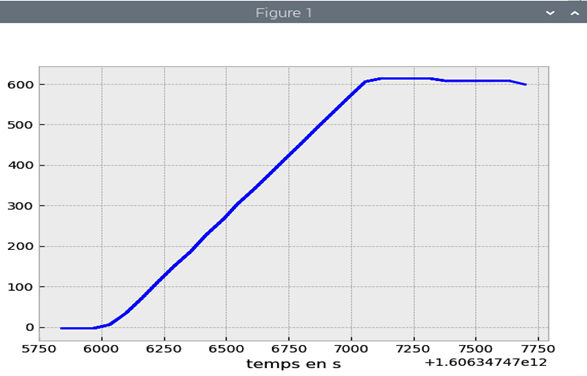
The following photo represents result of the PID on the position for angle 600 on a servo motor ST1 of the arm, I want to display the position steady state error signal;
then please you can give me the instruction or program to display the steady state error signal from the position knowing that I am using python software.
The steady state error would be the absolute value of the difference between the position reported by the encoder and the target position. Therefore, you can query the position of the servo when it’s in steady state (with the QD command) and subtract the target position (600) and the steady state error would be the absolute value of that.
Could you provide more information about this ? Are you looking to create a graph for the positioning error on Python ?
If that’s the case, we suggest you to look online for Python plotting tutorials. For example: