Same problem hete. Any news?
Do you have a photo of what the whole thing looks like all together on a robot because I’m confused about where to put everything and what I need so I photo might help
Hello everyone,
I just bought the sensor kit and I was very happy to have found such a nice and easy to use kit. After soldering (unfortunately there was already a capacitor missing but luckily i bought two kits so i took the one from the second kit) I tried to connect the sensor to my arduino and check the values. But my serial monitor only showed numbers in the range of 780 even after holding the inductor directly to the perimeter cable. My question now is what could I have done wrong. I am 100% sure I’ve soldered everything correctly. I also tested every possible state of the potentiometer while holding the inductor over the cable. The values didn’t change. Did anyone have the same problem or has a possible solution for me? I’m really struggling because I can’t imagine whats wrong other than the NE555 or the amplifiers being broken but I don’t know ow to check this. Thanks in advance for anyone trying to help me.
I had wanted to buy the kit but postage was expensive. I have a landroid and wanted to have several loops in different places. Earlier it said there was no way to know whether the robot mowere was in or out of a loop. However,Some / Slow progress | Details | Hackaday.io gives some insight into this though I do not understand it. There seem to be more than one sensor in landroids or some of them. How to check wire's sensors on Landroid
If someone could explain how this works it would be great.
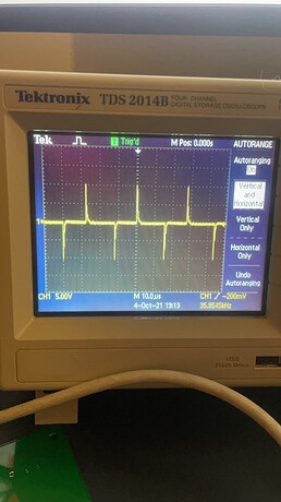
I notice that the output signal from the NE555 timer is a square wave. However when the output on pin 3 goes through the RC circuit it creates a signal that undergoes exponential decay. I was wondering if this was intentional or if I have done something wrong. I can still sense the wire with the receiver. Wondering why the resistor and capacitor were added to output. Was it to limit current?
Hi all. I couldn’t get a 4.7 K potentiometer. Is it ok to use a 5k one instead? Thanks
Sorry to sound naive, but from the drawings, I can’t see if you are using the inductor as an aerial or if the small copper coil - which appears to be parallel to 1mh and C couple - is the aerial.
I have found this kit very useful in making an RC car drive around the yard autonomously. However, I’m getting about 10cm of wire sensing range which is insufficient to drive at the desired speed. Is there any way to increase the range? Maybe a FET being driven by the 555 timer? Or an additional op-amp in series on the receiver?
Also, what is the purpose of the C5 capacitor on the generator?
Thank you!!!
has anyone tried to build it? it works?
hello, first of all I just want to thank you for putting together this awesome project , second of all I’m taking a wak at it but I made some modification and I would love to hear your thoughts on the subject.
the LM324 worked great but it saturates at 4V on my circuit so I replaced it with a rail to rail OPamp , I also added an integrator circuit on the output to make it output a DC signal that made it easier to use.
I changed the amplification values on the sensor board and added resonance by adding a capasitor to the generator board wich increased the signal detecting zone.
one last thing I added 2 potentiometers to the sensor board to precisely calibrate the amplification .
do you think any of this was a good Idea and why. and what else would you like me to try.
thank you again this was lots of fun and I’ll let you know how the final product came out once Im done.
Hello, is it possible to get the gerber files?
I saw that on the website there is an information “The files (Schematics, Eagle Files, Gerbers, 3D Files and Arduino Sample Code) are also available for download.” but “Files” section is nowhere to be seen.


