

I just purchased this from RobotShop. It’s one thing for there to only be “light” documentation. But none? Is there a document anywhere that explains the purpose, for example, of the pushbuttons on the HX711 board? I mean… y’know, there’s a kind of basic level of docs, no?
Hello @AlexM!
You can find the documentation here:
https://wiki.dfrobot.com/HX711_Weight_Sensor_Kit_SKU_KIT0176
Thank you for the feedback, we updated the product description to include the documentation.
Thanks, @geraldinebc15! I did find this wiki. Only problem is that everything I’m building is on RaspberryPi in PYTHON. Any idea if anyone has a library and instructions for working with this in PYTHON? There are many HX711 Python libraries out there but it turns out that this board is not actually a pure HX711 as it has a microprocessor and does I2C. Are you aware of something for we PYTHON people?
Alex
Hi, the following resources may help you.
Hi, @rpiloverbd. Thanks for the pointers. However, I have learned something important after 2 MONTHS of suffering with this: This kit sold by RobotShot keeps referring to it having an HX711 but the board that is included in the kit is apparently NOT an HX711, or, at least, it’s not a “standard” one. The board that comes with this kit has a microprocessor onboard and does NOT communicate with the RPi that way HX711 does. Instead, it uses I2C. I think that’s fine but man oh man would it have been nice if that was better documented. I haven’t gotten it to work yet, but this seems like a library properly designed to handle this specific board…
I wish the RobotShop folks would document their hardware just a wee bit better.
Thanks!
Alex
Hi Alex!
Thank you for your feedback.
Based on your comments we will add “I2C” to the product name and include the repository you shared on the Useful links section.
Please let us know if you are able to use the sensor.
Regards
Thanks a lot for your effort and feedback. It will help many users to get out of confusion in the future. Thanks to geraldinebc15 for a positive response.
I’m glad, guys. I have not been able to get this work, quite though. The Python version of this library is in mediocre to poor condition. I had to clean it up so that it would even work in Python3, and then its documentation is close to zero. Moreover, your board, itself, has these two buttons on them: “Gravity” and “I2C.” What do those buttons do? I don’t know. Long story short: If one wants to use this package on a Raspberry Pi with (modern) Python, they should be warned: It’s a huge slog. I’m now getting values back from the library, but I have no idea what they mean and I’m hardly in a position yet to be using this as a scale of any kind.
I’d be happy to upload my code (which, other than the library is incredibly simple) and the output I’m getting, but this Forum doesn’t seem to support uploads.
I really would like to get this to work so I can buy a bunch of them for use in this project, but I cannot get past the starting point.
I can see in the wiki page that one button is named ‘Cal’ which is for automatic calibration. Another is ‘RST’. After pressing the ‘RST’ key, no matter how many objects are placed on the sensor, the sensor will clear the current weight value. By the way, if this forum does not support upload, you can upload your code to github and share the link here. It’s totally up to you 
Hi Alex,
We are sorry you haven’t been able to make the sensor work.
If you are unfamiliar with “Gravity”, it refers to a series of boards compatible with micro:bit and Arduino, you can find more information about it here:
https://www.dfrobot.com/gravity.html
As this board is meant to be compatible with these microcontrollers the documentation is mostly for these (and the supported languages). Python isn’t a language supported on these microcontrollers, this is why there is not much documentation for it.
The Gravity button is simply to change the mode, in your case you should use I2C

You should be able to upload files on the forum, however, if you aren’t you can simply share a link (like rpiloverbd suggested).
If your goal is to work with a Raspberry Pi then I would suggest a different board, for example:
And if you want a make with multiple load cells this could help:

https://learn.sparkfun.com/tutorials/load-cell-amplifier-hx711-breakout-hookup-guide
In terms of Python support, there’s this library:
I hope that helps!
@geraldinebc15 - Thanks much for all of this. I’ll admit, I’m kinda lost with this board using RaspberryPi4 and Python so I definitely want to take your advice and switch to another board. You recommended this one (HX711 Load Cell Amplifier - RobotShop) and I’m just gonna buy it! BUT, I want to see if you can answer a thing or two for me first:
-
On the image it has RED, BLK, WHT, GRN, and YLW on one side. I assume that’s for the load cell, right? But the load thing I have (which I bought as part of the previous purchase) only has 4 wires. All of those colors except no YLW. Will that work? Do I just skip the YLW? Or do I have to buy a new load cell with this new board?
-
On the other side it has 5 connectors (VDD, VCC, DAT, CLK, GND). I looked at the Data Sheet and I’m just not enough of an engineer to penetrate it. While GND is obvious, not sure where the other 4 go on the RaspberryPi. I’m assuming 2 or 3 of the others go to GPIO pins that I will then set in the HX711 Python code you pointed me to, but I really don’t know what’s what.
I apologize for all the text, I am just sort of at my whit’s end trying to create scale functionality on a RaspberryPi4 in Python3. I’ll buy whatever, but I need instructions within those parameters and, amazingly, I’m not finding them end-to-end. I promise that if you help me resolve this, I’ll do an and-to-end write up!
Thanks!
Alex
-
Yes, RED, BLK, WHT, GRN, and YLW are for the load cell.
In general, each load cell has four strain gauges that are hooked up in a wheatstone bridge formation as shown below.
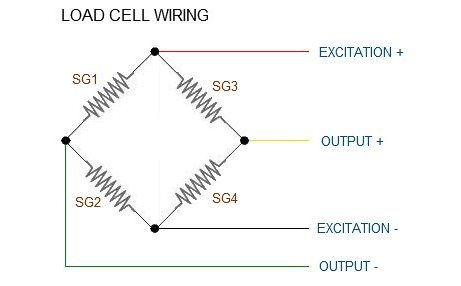
Some load cells might have slight variations in color coding such as blue instead of green or yellow instead of black or white if there are only four wires (meaning no wire used as an EMI buffer). You might have to infer a little from the colors that you have or check the datasheet on the load cell, but in general you will usually see these colors.
You can find more information about this here:
Load Cell Amplifier HX711 Breakout Hookup Guide - learn.sparkfun.com -
Here’s an example of how it is wired on an Arduino based board (VDD and VCC are for power, GND is ground)
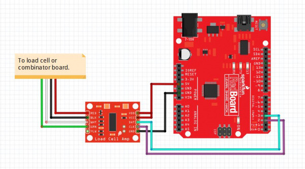

The other pins are DAT (DOUT) and CLK (SCK), for these you can use the ones suggested on the Python code I shared (line 49-50)
I apologize for all the text
Don’t worry, I’m here to help 