Nice! 
I’ve been looking around the forums for a gaiting code for quadrapods and i came across this
viewtopic.php?f=8&t=6951&hilit=frame+design&start=45
unfortunately im only using BAT pro with BB2 without the servo controller, is there any code around the forums that only uses BB2 for gaiting ?. im still searching around, no luck yet .
The servo controller has the magic stuff that makes gait construction doable with only a little processor horse power. Not to trivialize the code that does this, for example the Phoenix code (3DOF hex) is quite complex. But doing the gait and the servo pulse generation is a lot even for a 3DOF quad.
hmm, then i’ll need an SSC servo controller for the gait code ?, i wish i knew that a week ago so the shipment arrive sooner xD.
does the SSC-32 Servo Controller ships with its own V2 chip or ill have to order them separately ?
The SSC-32 comes with the latest chip and firmware. No need to upgrade a brand new board. 
and the servo controller is here 
now i only need the proper gaiting code. I was looking at Xan’s phoenix code recently “lynxmotion.com/images/html/proj102.html” and i have a few questions:
-
Is there an official code for quadrupeds or i’ll have to tweak Xan’s code to work on the quadruped ?
-
If the code needs to be changed, which area should i change exactly ?, i can read codes and try to figure out a way but you know how painful it is figuring out other people’s code, even when its well written like this one.
Thanks for the help 
Edit: Alright, i set the dimensions of my robot in the code and changed the 1st gait to be a simple walk 1 leg in the air at a time ( ignoring middle legs ), i saved the file and programmed the chip… Programming complete, i turn on the robot and all i hear is the sound of the speaker playing a note then the power led of the SSC keep flashing, the legs should snap to default position but that doesn’t happen, nor the PS2 controller has an effect on the robot.
im still trying to find a way to fix that, no luck yet.
bump is it a holiday ? 
Sounds like the PS2 is not connected properly. We sometimes use different pin for the PS2 interface. Alternate pins might require a pull up resistor.
Who’s on holiday?
Alan KM6VV
i rechecked the PS2 pins, i did just like this tutorial lynxmotion.com/images/html/build139.htm , still only a blinking SSC power led and no effect from P2 controller.
About the holiday part, i thought people were taking a break since there was no response for 2-3days 
Edit: one thing i noticed is when i turn on the robot the receiver is blinking then when i power the controller the blinking stops, so the controller is connected to the receiver, if there is a problem then its from the receiver not reaching the bot board or the BB not reaching the SSC.
There is no quadruped code available from Lynxmotion directly. Forum members may have something.
It would be awesome if we had some visual information with which to help guide our assistance… Post pictures!
What does it mean when the SSC power is flashing ? And I noticed that the code uses 38400 for baud rate while it says in the tutorial to set it for 115.2k, I tried changing the baud rate of the code, still no luck
The SSC led is not a power indicator, although it does turn on when you first apply power. It actually flashes when the SSC-32 receives data over the serial line. Note: the flashing does not indicate that the data is correct (including baud rate and the like), but simply that it is seeing something… If the code says 38400, I would suggest setting the SSC-32 to that baud rate to see if you get it to do something…
Later versions of the Basic Micro IDE does properly support 115200, but would suggest you start at the lower baud rates and get it to work first.
Need to read again through the thread to know which version of software you are using. Is it outputting the SSC-32 commands in AScii format or the newer Binary mode? What version of SSC-32 firmware you are using?
Kurt
My is SSC V2.03, i have the baud jumpers set to 38.4K. This the configuration part of the code :
[code];Project Lynxmotion Phoenix
;Description: Phoenix, configuration file.
; All Hardware connections (excl controls) and body dimensions
; are configurated in this file. Can be used with V2.0 and above
;Configuration version: V1.0
;Date: 06-10-2009
;Programmer: Jeroen Janssen (aka Xan)
;
;Hardware setup: ABB2 with ATOM 28 Pro, SSC32 V2, (See further for connections)
;
;NEW IN V1.0
; - First Release
;
;--------------------------------------------------------------------
;[SERIAL CONNECTIONS]
cSSC_OUT con P11 ;Output pin for (SSC32 RX) on BotBoard (Yellow)
cSSC_IN con P10 ;Input pin for (SSC32 TX) on BotBoard (Blue)
cSSC_BAUD con i38400 ;SSC32 BAUD rate
;--------------------------------------------------------------------
;[BB2 PIN NUMBERS]
cEyesPin con P8
;--------------------------------------------------------------------
;[SSC PIN NUMBERS]
cRRCoxaPin con P0 ;Rear Right leg Hip Horizontal
cRRFemurPin con P1 ;Rear Right leg Hip Vertical
cRRTibiaPin con P2 ;Rear Right leg Knee
cRMCoxaPin con P4 ;Middle Right leg Hip Horizontal
cRMFemurPin con P5 ;Middle Right leg Hip Vertical
cRMTibiaPin con P6 ;Middle Right leg Knee
cRFCoxaPin con P8 ;Front Right leg Hip Horizontal
cRFFemurPin con P9 ;Front Right leg Hip Vertical
cRFTibiaPin con P10 ;Front Right leg Knee
cLRCoxaPin con P16 ;Rear Left leg Hip Horizontal
cLRFemurPin con P17 ;Rear Left leg Hip Vertical
cLRTibiaPin con P18 ;Rear Left leg Knee
cLMCoxaPin con P20 ;Middle Left leg Hip Horizontal
cLMFemurPin con P21 ;Middle Left leg Hip Vertical
cLMTibiaPin con P22 ;Middle Left leg Knee
cLFCoxaPin con P24 ;Front Left leg Hip Horizontal
cLFFemurPin con P25 ;Front Left leg Hip Vertical
cLFTibiaPin con P26 ;Front Left leg Knee
;--------------------------------------------------------------------
;[MIN/MAX ANGLES]
cRRCoxaMin1 con -260 ;Mechanical limits of the Right Rear Leg, decimals = 1
cRRCoxaMax1 con 740
cRRFemurMin1 con -1010
cRRFemurMax1 con 950
cRRTibiaMin1 con -1060
cRRTibiaMax1 con 770
cRMCoxaMin1 con -530 ;Mechanical limits of the Right Middle Leg, decimals = 1
cRMCoxaMax1 con 530
cRMFemurMin1 con -1010
cRMFemurMax1 con 950
cRMTibiaMin1 con -1060
cRMTibiaMax1 con 770
cRFCoxaMin1 con -580 ;Mechanical limits of the Right Front Leg, decimals = 1
cRFCoxaMax1 con 740
cRFFemurMin1 con -1010
cRFFemurMax1 con 950
cRFTibiaMin1 con -1060
cRFTibiaMax1 con 770
cLRCoxaMin1 con -740 ;Mechanical limits of the Left Rear Leg, decimals = 1
cLRCoxaMax1 con 260
cLRFemurMin1 con -950
cLRFemurMax1 con 1010
cLRTibiaMin1 con -770
cLRTibiaMax1 con 1060
cLMCoxaMin1 con -530 ;Mechanical limits of the Left Middle Leg, decimals = 1
cLMCoxaMax1 con 530
cLMFemurMin1 con -950
cLMFemurMax1 con 1010
cLMTibiaMin1 con -770
cLMTibiaMax1 con 1060
cLFCoxaMin1 con -740 ;Mechanical limits of the Left Front Leg, decimals = 1
cLFCoxaMax1 con 580
cLFFemurMin1 con -950
cLFFemurMax1 con 1010
cLFTibiaMin1 con -770
cLFTibiaMax1 con 1060
;--------------------------------------------------------------------
;[BODY DIMENSIONS]
cCoxaLength con 37 ;Length of the Coxa [mm]
cFemurLength con 90 ;Length of the Femur [mm]
cTibiaLength con 79 ;Lenght of the Tibia [mm]
cRRCoxaAngle1 con -450 ;Default Coxa setup angle, decimals = 1
cRMCoxaAngle1 con 0 ;Default Coxa setup angle, decimals = 1
cRFCoxaAngle1 con 450 ;Default Coxa setup angle, decimals = 1
cLRCoxaAngle1 con -450 ;Default Coxa setup angle, decimals = 1
cLMCoxaAngle1 con 0 ;Default Coxa setup angle, decimals = 1
cLFCoxaAngle1 con 450 ;Default Coxa setup angle, decimals = 1
cRROffsetX con -89 ;Distance X from center of the body to the Right Rear coxa
cRROffsetZ con 89 ;Distance Z from center of the body to the Right Rear coxa
cRMOffsetX con -63 ;Distance X from center of the body to the Right Middle coxa
cRMOffsetZ con 0 ;Distance Z from center of the body to the Right Middle coxa
cRFOffsetX con -89 ;Distance X from center of the body to the Right Front coxa
cRFOffsetZ con -89 ;Distance Z from center of the body to the Right Front coxa
cLROffsetX con 89 ;Distance X from center of the body to the Left Rear coxa
cLROffsetZ con 89 ;Distance Z from center of the body to the Left Rear coxa
cLMOffsetX con 63 ;Distance X from center of the body to the Left Middle coxa
cLMOffsetZ con 0 ;Distance Z from center of the body to the Left Middle coxa
cLFOffsetX con 89 ;Distance X from center of the body to the Left Front coxa
cLFOffsetZ con -89 ;Distance Z from center of the body to the Left Front coxa
;--------------------------------------------------------------------
;[START POSITIONS FEET]
cRRInitPosX con 117 ;Start positions of the Right Rear leg
cRRInitPosY con 79
cRRInitPosZ con 117
cRMInitPosX con 105 ;Start positions of the Right Middle leg
cRMInitPosY con 25
cRMInitPosZ con 0
cRFInitPosX con 117 ;Start positions of the Right Front leg
cRFInitPosY con 79
cRFInitPosZ con -117
cLRInitPosX con 117 ;Start positions of the Left Rear leg
cLRInitPosY con 79
cLRInitPosZ con 117
cLMInitPosX con 105 ;Start positions of the Left Middle leg
cLMInitPosY con 25
cLMInitPosZ con 0
cLFInitPosX con 117 ;Start positions of the Left Front leg
cLFInitPosY con 79
cLFInitPosZ con -117
;--------------------------------------------------------------------[/code]
im using BasicMicro studio 2.0.0.15 to program the BB
We’ve been trying to help you, but you refuse to post any images. Posting a few simple images can definitely save us an enormous amount of time typing the same old questions…
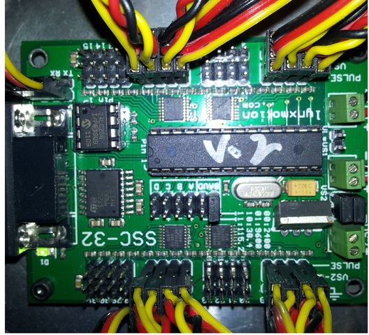
Sorry about that, here is a picture of the SSC
That’s a good start… How we need to see the power wiring, battery, microcontroller, etc.
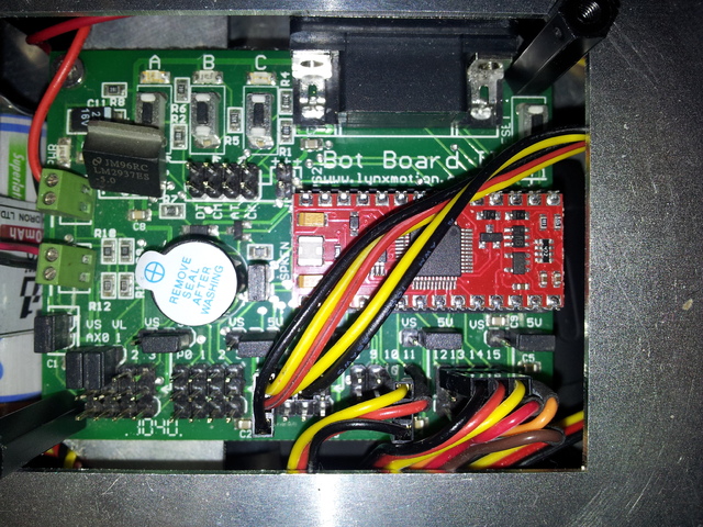
this the micro controller, the wires in the middle terminal goes to ssc VL
The pins 4,5,6 are for the accelerometer . The 9v battery and the receiver are under the board, to the left edge you can see a part of the 5 cell Ni-MH batter that is connected to the VS1 terninal in the SSC
So far from what you are saying, I can not tell if your issue is hardware or software. You say your SSC-32 is running the 2.03 version of the firmware. So it is safe to say that it does not support binary mode. So then it depends on what version of the Phoenix software you are running on your robot. Some of the earlier 2.0x versions we had some #ifdef to enable Binary mode output. In the newer 2.1 Phoenix code we only have the binary output.
The Older Text command source code looked something like:
The Binary code looks something like:
serout cSSC_OUT, cSSC_BAUD, "#",dec cCoxaPin(LegIndex) ,"P",dec (-CoxaAngle1(LegIndex) +900)*1000/1059+650]
Note: the “#” and the like. Where the binary output will look something like:
    serout cSSC_OUT, cSSC_BAUD, [0x80+cCoxaPin(LegIndex) ,CoxaPWM.highbyte,  CoxaPWM.lowbyte,|
    	                         0x80+cFemurPin(LegIndex),FemurPWM.highbyte, FemurPWM.lowbyte,|
    	                         0x80+cTibiaPin(LegIndex),TibiaPWM.highbyte, TibiaPWM.lowbyte]
If you are not sure, or to enable the new functionality, I would recommend you update the Firmware in the SSC-32 to version: 2-07EGP_A1A.abl
Which you can download from: lynxmotion.com/p-395-ssc-32- … oller.aspx
Kurt
A strange error appears when trying to update the firmware :
I tried the jumper method but i keep getting an error saying “Error ! verifying address : 3500 (Hex)”.
i also got the same error but with different address when i tried re-updating to V2.03.
Edit: Ah there we go, i had to update that at 115.2k baud rate, now its all good. There seem to be a little progress, when i power the robot the servos snap randomly to a position then go off. Ill keep trying out different things and post the progress


