I m such a newbie, please forgive me.
I have the picaxe 28x1 starter pack and i'm trying to do the "Test the System" tutorial, but im am so lost.
When it says 'connect to pin 4' i notice there are two pins side by side on #4, which pin do i actually connect to ?
do i have to connect both? Been using the pin closest to the Darlington chip, with out success.
Also there are two 'v' pins on oposite sides of the board, which one should i use? or does it matter .
I have my 330R and my led on a bread board, but can't get it to blink, even though i am getting current form the Picaxe board,
I checked with my volt meter,
The sketch was successfully uploaded to the board, that much i can do correctly.
Maybe someone kind enough could upload a pic of how it's suppose to look.
Thanks and much kudos in advance.
Please review the 28 pin
Please review the 28 pin Project Board walkthrough by Frits. Note that the pins close to the chip are the output pins, and the next row is V+ if the jumper is installed towards the bottom right corner. Check voltage on the second row to make sure it is at V+ (4.5 volts). The LED should have the short lead wired to pin 4, and the long pin wired through the resistor to the V+ pin beside it. It is also possible to connect the LED backward so it will not light, try it both ways.
Thanks for the info it was
Thanks for the info it was actually helpful.
I think i have it hooked up right but i stil can’t get the led to blink.
so i took some pics of my picaxe and breadboard
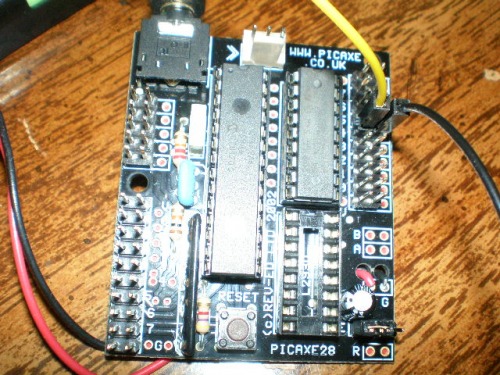
Yellow wire is the pin 4 out put and the black is V
I know from the angle it looks like i have the yellow connected to pin 5, but it's actually pin 4.
I've also tried connecting V on the bottom of the darlington chip(bottom left).
When i use my volt meter i get voltage from pin4 and V also from the wire leads, it fluxuates between 4v and 0v
as it should since it's turning on and off, right ?
I checked the led with an led checker and it works, i tried a different bradboard thinking maybe the one i was using was damaged, but still no blinking led.
i have checked the polarity of the led and i think its right, the short end is connected to the yellow wire
which is connected to pin 4, i tried the other way round just in case, but no.
I am stumped, i must have somthing connected wrong
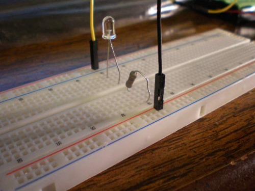
You need to learn what a breadboard is
None of your components are actually wired together. I don’t how to explain in words how a breadboard is wired.
The outside holes, that run along the blue line, are all connected together, but only on each side. In other words, the “blue line” holes at the top are NOT connected to the “blue line” holes on the other side.
Same goes for the “red line” holes.
Use your meter and buzz out the breadboard so you can see how the holes are connected.
Simple enough.
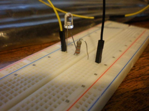
What everyone is trying ot say is that your yellow and black wires are plugged into what are usally used as "power rails". Just leave everything where it is, but scoot your outside led leg and the outside resistor leg in (to the center). Now scoot your yellow and black wires to these holes. --You are just moving everying one hole to the center and thus, getting your yellow and black wires connected to the "main board" not the outer-laying power rails.
Power rails…
By the way, on those “power rails”… all the holes under the blue line are connected. all the holes on the red line are connected. If you had power going to the breadboard to power your project (your power is comming from the 28x board) you would connect + to the end red-line hole and ground to the end blue-line hole. This way, while connecting the circuit you are working on, you have as many power connections you would need insteading of jumping power from pin to pin to pin all over you otherwise nice, tidy circuit. Also, the top and bottom "power rails’ are not connected together.
Big Thanks…but
AHA! it was the breadboard, oh umm maybe it was me,
Now i know better, however i still can’t get the led to blink.
I don't know what's up now, i'm about to give up, i'm getting current from the picaxe(fluxing between 4 and 0), so the picaxe is working i guess,
I just can't get current to the led, i've switch out the resistor with a new one, thinking maybe the resistor was bad, but still no blinking led.
Thanks
I finally figured that out.
I had a, DOH! moment when it worked.
late
TADAA!! you made it!welcome,
TADAA!! you made it!
welcome, to the world or robotics! (more or less :D)
i started as you, compele newbe, and now i do more and more advanced stuff all the time! and what you got there(picaxe 28x1), is powerfull enough for advanced robots!
and now you got a handle of it you should see this


