I built a quadrapod using a printed chassis, botboarduino, SSC-32 servo controller, PS2 V4 controller, 7.2V battery pack, and 12 SG90 servos. I used a copy of the quad Phoenix code for symetrical quads. I still need to adjust the program a little bit more and I need to find some stronger servos, perhaps some MG90s. Its not strong enough to carry its battery pack lol. Thank you for all the help I recieved regarding the technical stuff.
Best regards,
Good job! Some stronger servos definitely won’t do any harm!
At first I thought you were powering the whole thing with a 9V battery until I saw the battery pack on the floor hehe
If you want to reduce the weight of the battery pack, you should consider switching your NiMH to LiPo.
Keep us updated!
Thank you for the info! I didn’t know that LiPo batteries were lighter. This chassis was designed for an arduino nano. But I have the botboarduino and the SSC-32 on board along with that big battery pack. Right out of the gates it broke a couple servos. I get alot of servo vibration too. I’ve tried installing a couple chokes on the femur servos with no luck. When there is no load on the servos, it can vibrate really bad. I’m hoping stronger and better quality servos will help.
Best regards,
-Adam
In your case, better quality servos will help for sure. You can also read a bit about “hunting” but I’m not sure it will fix your problem.
Hunting: https://electronics.stackexchange.com/questions/126295/servo-does-not-stop-in-a-stable-position
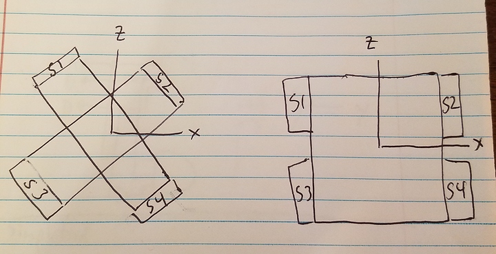
Well I got some stronger metal gear servos in the mail and I put some o-rings on them to help with the vibration. Today I am going to install and align them before a test walk with the quadrapod robot. I have a question regarding the symmetry of the robot I built regarding how the phoenix code is affected by the angles of the servos I have in the coxa position. The LSQuadA code was setup for a robot that has the Coxa servos at 45 degree angles. My robot has the coxa servos at angle 0. I drew a quick sketch of the robot diagrams to represent how my robot differs from the symmetrical quad. I have been making adjustments to the hex_cfg.h file with some success. But the question is do I need to make adjustments to the Phoenix.h or the Phoenix_code.h files? I have been looking through both of these two files and they are very complicated and difficult for me to understand. Should I be able to make all the necessary leg adjustments using just the hex_cfg.h file? Can I add some #define to the hex_cfg.h file to represent some new criteria regarding the location or angle of the coxa servos?
Best regards,
Adam
Most of the time if buying low cost LiPo packs vs low cost NiMH packs, the LiPo ones will have a lower weight for similar capacity & discharge rate. You can read a bit more about it here, here and here.
Definitely stronger servomotors are needed for carrying such a large battery pack which is required to move to many servos… but having stronger servos will use more current and therefore need bigger battery pack which will…  Anyone else thinking of the rocket equation? Ok ok, it’s not that bad!
As a reference, most of the larger Lynxmotion hexapods use at least the HS-645MG [RB-Hit-29] which produces 7.7~9.6 kg-cm (4.8-6.0 V DC) of stall torque. Of course, you an get stronger ones in a similar form factor, such as RB-Hit-120 which has 17 kg-cm of stall torque.
It would be good to know which code you are using as a base. Would it be this one (Quadruped) or this one (Hexapod 3/4 DoF)?
Also, did you make a fork with modifications? If so, please include a link to it here! 
It may be possible to rectify the motion of the gait to fit your different placement of the servomotors by modifying only the code’s settings (in the .h files). I actually do not know if that will be enough. You’ll need to investigate more and see if it is (settings). You may also want to have a look at the code that generates the positions of the servos for the gait and how it uses those settings.
Welcome to robotics!  More seriously, the main job of software developers (aside from actually designing software systems/implementing it) is to reduce complexity. That being said, most problems have inherit complexity (such as inverse kinematics and gaits) and therefore dealing with this inherent complexity will often yield complex results (such as that Phoenix code implementation). It also has the added complexity of running on a low power, low clock speed, 8-bit microcontroller with no hardware division…
You can only “add” (modify existing ones or add missing ones) #define that are known to the code: i.e.: that are expected. You can certainly add brand new #define if you want but you’ll have to modify the inverse kinematic code to use them… 
All considered, it feels like the settings concerning coxa angle and starting position of the feet should be helpful here.
My quadrapod is coming along very nicely. I have a real nice walking gate working now. However I have some other problems that I need help with now. I have been burning up servos and I’m now sure if its because I’m using 7.2V or if the robot weighs too much or a combination of the both. I’m using a 7.2V Nimh 1200mAh battery and it’s pretty heavy for the small servos I’m using. I think I need a 7.4V Lipo battery which is considerable lighter and use that in conjunction with a 6V regulator. My quadrapod uses 12 servos that have a moving no load amperage of 1A, some data sheets say 320mA, so I’m not sure which is accurate. So im thinking about getting the 6V 15A regulator, or at least a 5A 6V regulator, I need to measure the amperage draw since the data sheets have conflicting amperage specs. Does this sound like a good plan?
Hey,
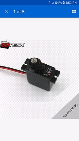
Yeah, the specs shown here for the GS-D9025MG seem to indicate a voltage range of 4.8-6.0 V DC. Using 7.2 C DC would most certainly cause issues.
Your motors have a rated torque of 2.5 kg-cm, which is most likely really far from being enough.
As mentioned before as a point of reference the recommend motors for a basic Lynxmotion 3 DoF hexapod kit with a NiMH battery pack is the HS-645MG [RB-Hit-29] which produce 9.6 kg-cm @ 6.0 V DC. That’s nearly 4 times the torque and some customers still opt to use stronger motors still.
Most definitely both.
The more current you use, the higher the voltage drop from a regulator. Of course, some regulators can handle it better than others. I recommend using a 3S battery pack (11.1 V DC nominal) so as to prevent a slightly discharged pack of causing issues with voltage.
Most LiPo cells are considered discharged at ~3.0 V DC (critical voltage / need to cut off usage). Even if you stop before that to be safe, lets say around 3.3 V DC (recommended), you’ll still have only 0.6 V DC of leeway for the voltage drop of your regulator. Having a higher starting voltage, the 3S pack would also last longer than a 2S.
You can find plenty of 6.0 V DC regulators here. A good option is probably the RB-Pol-467 6 V DC, 15 A regulator.
It should be noted this voltage regulator had a minimum operating voltage of 7.2 V DC (for small load) and the manufacturer specifies that this minimum increases with load up-to 7.6 V DC for 15 A loads.
Therefore, if you expect to use 10-15 A, you will most definitely need a 3S (11.1 V DC) battery pack for this regulator. In this range of power (5-15 A) you will most likely have similar requirements with other regulators, too.
Not as-is, no.
A good plan would be:
-
Stronger motors. Probably at least double or more torque. Don’t forget that the rated torques you see are stall torques (where the motor burns up and dies quickly), not useful torque. As a rule of thumb, expect to not be able to use more than 20-25% of the stall torque continuously without damaging you servomotors. And at that, maybe for no more than 20-30 mins at a time with cool down periods between (plastic cases prevent faster cooling thus reducing usable duration).
-
Provide the proper voltage to the servomotors. Since most of those require 6.0 V DC providing a higher voltage will damage them (over time or instantly, depending on how much). Using a high 6 V DC power regulator is a great idea but you’ll need a much higher voltage for it to work out (as discussed above). Of course, using a higher voltage makes the motors heat up faster and can even just outright destroy on-board control electronics, too, depending on the components it is made of.
-
A battery pack that provides enough voltage from fully charged to discharged for the regulator so it does go below its minimum voltage requirements (such as a 3S LiPo of a nominal voltage of ~11.1 V DC).
Here are some example battery packs:
11.1V, 3500mAh, 3S1C, Li-ion Battery
11.1V, 2500mAh, 30C LiPo Battery
11.1V, 3000mAh, 40C 3S LiPo Battery
11.1V, 3500mAh, 30C LiPo Battery
11.1V, 4000mAh, 40C 3S LiPo Battery
I hope this helps!
Sincerely,
hi can you tell me more about you bot
Certainly. Here is a link to a video that shows what I have built. https://youtu.be/o_r3Lywxt9U
I’m using the Botboarduino in conjunction with the SSC-32 servo controller and the PS2 V4 gamepad controller. The chassis is a common frame 3d model available online. I had one of my friends print it out on a 3D printer he owns. This current hardware set up typically demands that I use more powerful servos than the GS-D9025MG I’m using but I’m trying to cut weight by using I lipo battery. I had a real heavy NIMH battery on board and it was just too heavy for the servos to be continuously supporting. With that and along with the fact that i was using a 7.2V battery with 6V rated servos, i had burned out a couple servos. So it still a work in progress. Best regards.


