

My robot uses the exact
My robot uses the exact motors (2 of them) you describe there controlled via the adafruit motorshield powered by 4AA batteries (the arduino is powered by a 9v). So you should be fine there if you decide to go the motorshield route.
Not rocket science
Well like I said using an L293D (or similar) isn’t exactly rocket science. The links I provided here pretty much cover it.
This should give a basic understanding of what an H-bridge is:
www.mcmanis.com/chuck/robotics/tutorial/h-bridge/index.html
This explains how the L293D chip works:
dev.emcelettronica.com/microcontroller-motor-interface
Here is the pin out for the chip (and others that are pin compatible):

Also the Arduino playground has some examples on how to hook it up:
www.arduino.cc/playground/Main/InterfacingWithHardware#Output
And the Arduino forum (as well as this forum) is filled with people who are willing to share their knowledge and answer questions:
www.arduino.cc/cgi-bin/yabb2/YaBB.pl
One of the greatest assets of the Arduino platform is its community :)
The only thing that is
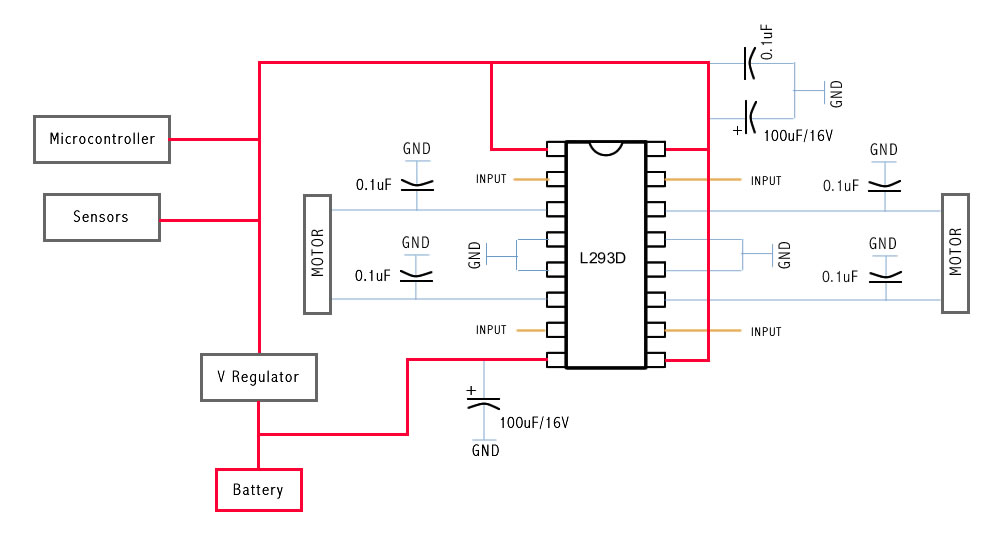
The only thing that is giving me a major major headache at the moment is: (Please excuse me if I am being stupid) Do I need capacitors & voltage regulators as shown here: http://farm4.static.flickr.com/3524/3235658022_7f505922e3_o.jpg
If I do need them how come most other L293D guides don’t show it or is it not needed thats why I’m confused. Am I supposed to like sort of know there must be a capacitor there?
Also the grounds, do they just go into nothing (blank hole) I know what ground means and all but I’m not sure how it works on a PCB etc.
Sorry to trouble you guys but I need to understand this : <
Ah! The cap issue 
The Arduino allready has a voltage regulator so don’t worry about that. And atleast 2 of the caps in the circuit you linked to are there to support the voltage regulator. The L293D will work without caps, however it is recommended to use caps to smoothen out the current flow. Here is a good article about why caps should be used in various circuits:
www.thebox.myzen.co.uk/Tutorial/De-coupling.html
Unfortunately there are no rules to how many, which kind or even where to put them. Everybody seems to have their own way of using caps. The circuit you mentioned is one way. But here for instance they recommend soldering the caps directly between the motor terminals OR from a terminal to the motor casing (?).
I have the same doubts as you…being an IT nerd who’s new to electronics. I bought an L293D a few days ago and seemingly it works fine without any caps. It also depends on which motors or power supply you’re using and how many other things you’re powering from the same source. I bought a batch of 0.1uF ceramic caps that I’ll try to put in different places if my setup starts acting unstable at some point.
And about the grounds…They don’t exactly just go into a black hole. The ground is the negative pole of a dc power source. The current flows from the positive pole to the negative pole. If it’s not connected to the ground there is no circuit. In this case there are 2 grounds. The Arduino ground AND the external power supply’s ground. BTW it’s important that these 2 grounds are connected since they form a circuit together…
That’s my 5 cents 
Just a follow up
I just made my own motor shield as you can see here.
And so far it works fine with NO caps. Perhaps cause the motors I’m using are very small. I dunno. I did however solder a cap directly on the motors between the terminals as suggested in the link I posted earlier.
Just though you should know that making your own shield isn’t as hard as you may think