

VIDEO!!!
Well, video is up. I dont show anyone sitting on it because I'm the only person who knows how to controll it and I had to shoot the video, so I just let it walk solo. Enjoy :]
BTW at the end one of the neighbors is like "whats that?" so I, (almost startled) say "um...robot" and the video ends...
June 5, 2009 Update:
Well I never could get a video...yet. I'm doing some repairs and upgrades today, and rebuilding the control box. WITH ANY LUCK it'll stop raining here and I can shoot a video on our new, flat, and level driveway ( hehe :] ). I must say however that I am disapointed at how ugly it truly is...especially compaired to this: http://basicrobotics.net/mech.html
WOW I need that thing... I'm seeing an expensive new project coming in the next few months.....
But I'm not done yet. These actuators are AMAZING. I'm going to figure out how to build a more efficient, better looking frame with whatever money I can save up. Then just transfer the actuators, and bam, WIN.
QuickUpdate:
OK the brand new batteries already died. I put a 10 amp car fuse to regulate the amps, too. I have an 18 volt drill battery on it (6 volts more than supposed to) and it still walks frustratingly slow. You can't even tell its walking on video. But on the good side, I made an brilliantly designed way of controlling it without anything more than tape, wires, tin foil, glue, and a box.
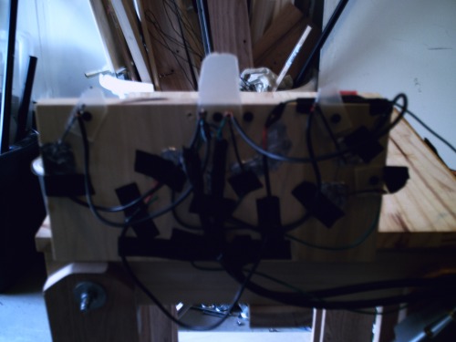
Here it is (It has 1 big switch for back and forth motion, two for independent side control to recalibrate, and one master cut-off switch): I know its hard to make it out, its very complex and immaturely built, plus lighting is bad.
UPDATE3:
It walks! I am sooooooo happy! My actuators came today, and I've been pondering forever on how to get it all together safely... And it all paid off. Test 1 was a 50% sucess, because the wheels gave in to the twisting motion of the legs. Tests 2 and 3 were 90% sucess, because it walks, but it walks backwards (although technically I never even defined a front or back yet, seemg how its a square...)
It held my weight, and walked flawlessly. I will post a video tomarrow! Thanks for sticking with me!
UPDATE2
Ok, sooo close. I have the money. I finished the frame. Now I just need the actuator. I found a pair of cheap, 250 lbs actuators, 85 lbs stronger than the last one I chose. In less than two weeks I'll have it done and walking...
I also updated specs. Instead of a rechargable battery, I chose alkaline. It's cheaper, as my budget is shrinking. The new actuators are 250 lbs now, not 165. There are also no sensors like I had planned. And my idea to put 10 amp fuses on it probably won't happen, because the actuators only can go up to 5 amps. So that's it, stay tuned for more...!
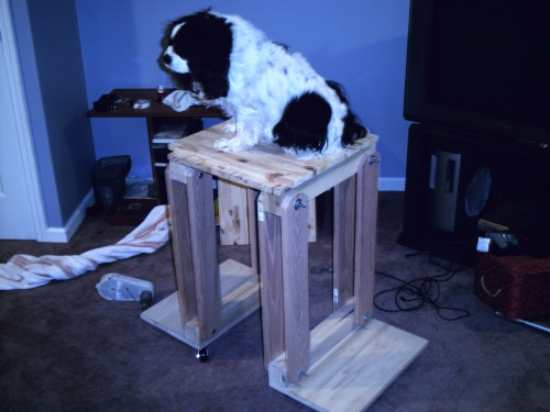
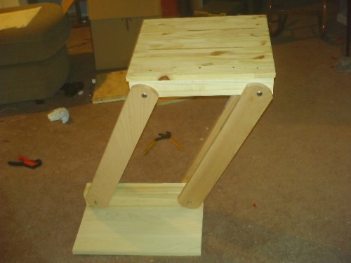
That's my dog Abby on the latest frame.
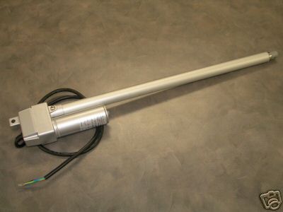
The new actuator model, capable of 250 lbs.
OLD:
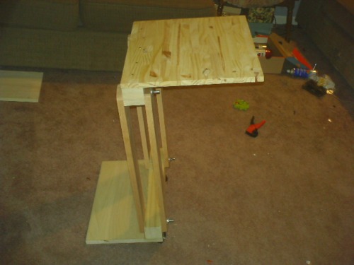
Side View
Front View
Extended View
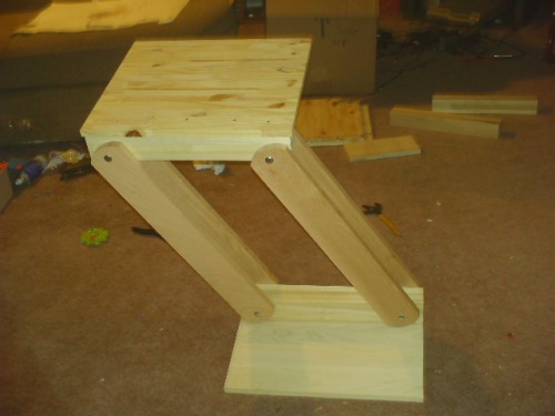
This is the first side of my "Mech"
It's hard to make out the shape chair yet because I only have 1/4 the parts so far... this project will be completed probably early May, but I'll update in the meantime.
This chair dubbed TP (or TS) is a walking chair, as in you sit i it and it walks (bipedal). Here's the CAD model of the final design:
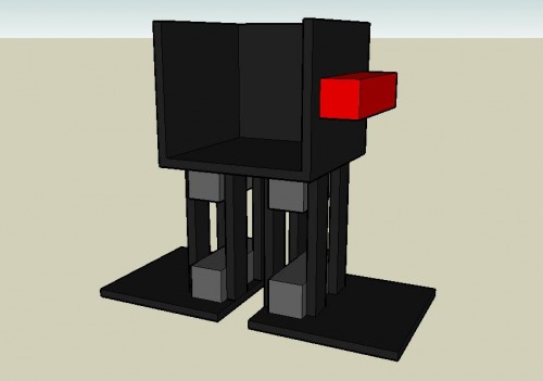
Neat, huh?
Bipedal Human Transport
- Actuators / output devices: 2 Linear Actuators Rated 250 lbs each
- Control method: Controlled
- CPU: none
- Operating system: none
- Power source: 2 Alkaline 6 Volt Batteries
- Programming language: none
- Sensors / input devices: none
- Target environment: outdoor
This is a companion discussion topic for the original entry at https://community.robotshop.com/robots/show/bipedal-chair-progress-not-finished-yet


