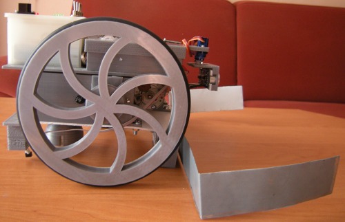
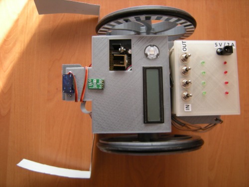
Béda 6 is a home-made robot, which we designed with my two brothers in the HaHaHa Robotics team for the Ketchup House competition at the Robotic Day 2016 in Prague. Everything worked better than expected and we won it over 10 other robots. The robot is a refurbished version of an older robot Béda 5 made for the RoboRAVE 2016 competition – Junior category (…which it won as well…). It uses mechanical parts, power system, geared motors, control board and sensors of original Béda 5, we just exchanged a top ball-collector for a front steel ploughshare and IR distance sensor with push-buttons for ultrasonic sensor (rotating on a servo for an opponent detection).
Function:
In the Ketchup House competition, two autonomous robots try to gather up to 12 ketchup cans on a playing field composed of a 7x7 black line grid and place them on their home lines. The robot cannot push the opponent out of the playing field but it can seize the cans from the opponent´s home line. The robot collecting more cans than the opponent in a 3-minute time limit is a winner.
Description:
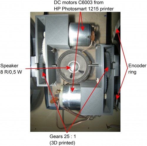
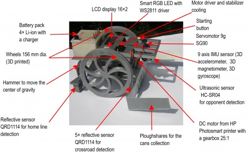
Béda 6 uses DC motors salvaged from HP Photosmart 1215 printer, mechanical parts incl. gears and wheels printed on a 3D printer, control system based on own PCB with PIC16F1789, bidirectional motor driver L298N (2x 2A), alphanumeric LCD display 16x2, RGB LED with WS2811 driver, 6 reflective sensors QRD1114 for following the black lines on the 7 x 7 playfield. Ultrasonic distance sensor HC-SR04 rotating on a servo-motor SG9z serves for the opponent detection on the field. The robot is equipped with 9D position sensor MinIMU-9 (3D accelerometer, 3D magnetometer and 3D gyroscope) from Pololu company, but the sensor was not finally used in the program. The robot is powered by a battery pack with 4 Li-ion 18650 accumulators 2.2 Ah charged with a chip MCP73831.
Mechanical parts:
- main wheels: Ø156 mm 3D printed at PRUSA i3, material PLA, a modified parametric model from http://www.thingiverse.com/thing:21486
- stabilizing ball wheel: ping – pong ball in a holder, 3D printed at PRUSA i3, material PLA, a model taken from http://www.thingiverse.com/thing:636967
- tires of the main wheels: a rubber sheet cut from an old washing machine
- chassis: polycarbonate sheet 120 × 250 mm from a HP DeskJet printer
- 2×gearbox 25:1, 3D printed at PRUSA i3, material PLA, a modified parametric model from http://www.thingiverse.com/thing:3575
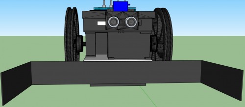
- holder of reflective sensors: 3D printed at PRUSA i3, material PLA, own design (see the SketchUp model in the attachment)
- the control board case with a lid: 3D printed at PRUSA i3, material PLA, own design (see the SketchUp model in the attachment)
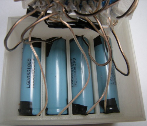
- the battery pack box with lid: 3D printed at PRUSA i3, material PLA, own design (see the SketchUp model in the attachment)
- holder of ultrasonic distance sensor: 3D printed at PRUSA i3, material PLA, own design (see the SketchUp model in the attachment)
Electrical parts:
- MCU: PIC16F1789
- MCU inputs:
· 5×reflective sensor QRD1114 for the black line following and crossroad detection
· 1×back reflective sensor QRD1114 for home line detection
· 1×reflective sensor QRD1114 for a wheel encoder
· 9-axis IMU sensor MinIMU-9 for robot orientation on the field
· ultrasonic distance sensor HC-SR04 for opponent detection
- MCU outputs:
· alphanumeric LCD display 16x2
· bidirectional motor driver L298N (2×2 A)
· RGB LED with a driver WS2811 for signalization
· servomotor 9g SG90 for ultrasonic distance sensor rotation
· speaker 8 Ω/0,5 W for playing the winning songs
- Motors: 2 DC motors C6003 salvaged from HP Photosmart 1215 printer
- Battery pack: 4×Li-ion acumulators 3.6 V/2.2 Ah, separately charged via MCP73831 chips
- PCB: universal line PCB e=0.1“
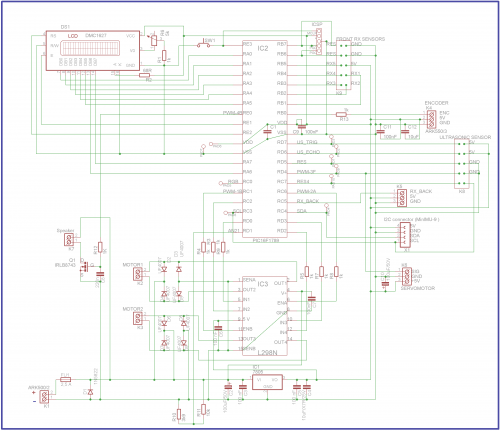
Control board – functional scheme (higher quality scheme is in the attachment):
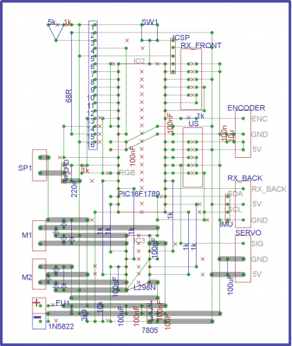
Control board soldering scheme on 0.1´´ line universal PCB:
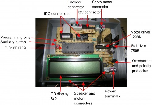
Table of components – Control board:
Code | Type | Parameters | Function |
C1 | capacitor | ceramic 100 nF SMD 0805 | MCU power filter |
C2 | capacitor | electrolytic 100 µF/50 V | 7805 input filter |
C3 | capacitor | ceramic 100 nF SMD 0805 | 7805 input filter |
C4 | capacitor |
ceramic 10 µF /X7R/25 V SMD 0805 | 7805 output filter |
C5 | capacitor | ceramic 100 nF | 7805 output filtration |
C6 | capacitor | ceramic 100 nF | L298N power filtration |
C7 | capacitor | ceramic 100 nF | L298N power filtration |
C8 | capacitor | ceramic 220 nF | speaker input RC filter |
C9 | capacitor | ceramic 100 nF SMD 0805 | MCU power filter |
C10 | capacitor | electrolytic 100 µF /50 V | servo motor power filter |
C11 | capacitor | ceramic 100 nF SMD 0805 | encoder input filtration |
C12 | capacitor | ceramic 10 µF SMD 0805 | encoder input filtration |
D1 | diode | 1N5822 | polarity protection |
D2 -D9 | diode | UF4007 | L298N output protection |
DS1 | LCD display | alphanumeric 16x2 | setting and displaying program parameters |
FU1 | polymer fuse | 2.5 A | overcurrent and polarity protection |
IC1 | stabilizer | 7805 | 5V power source |
IC2 | MCU | PIC16F1789 | microcontroller |
IC3 | motor driver | L298N | bidirectional motor driver 2x2 A |
| programming pins | ICSP | programming pins to MCU |
|
|
|
|
IMU | positional sensor | MinIMU-9 | robot orientation on the field |
K1 | terminal | ARK500/2 | main power connector |
K2 | terminal | ARK500/2 | motor connector |
K3 | terminal | ARK500/2 | motor connector |
K4 | terminal | ARK550/3 | reserve output connector |
K5 | terminal | ARK550/3 | back RX connector |
K6 | terminal | ARK550/3 | servomotor connector |
K7 | terminal | ARK500/2 | speaker connector |
K8 | connector | IDC10 | ultrasonic distance sensor connector |
K9 | connector | IDC10 | front reflective sensors connector |
MOTOR-MOTOR2 | motors | DC motors C6003 salvaged from a printer HP Photosmart 1215 | robot wheel drive |
PAD1 – PAD10 | soldering pins |
| auxiliary connectors for external inputs and outputs |
Q1 | transistor | IRLB8743 | switching speaker for sound generation |
R1 | resistor | 1 kΩ | LCD display contrast setting |
R2 | resistor | 68 Ω | LCD display background light |
R3 | resistor | 1 kΩ | L298N input protection |
R4 | resistor | 1 kΩ | L298N driver protection |
R5 | resistor | 1 kΩ | L298N driver protection |
R6 | trimmer | 5 kΩ | LCD display contrast setting |
R7 | resistor | 1 kΩ | L298N input protection |
R8 | resistor | 1 kΩ | L298N input protection |
R9 | resistor | 1 kΩ | L298N input protection |
R10 | resistor | 3.9 kΩ | voltage divider for battery control |
R11 | resistor | 10 kΩ | voltage divider for battery control |
R12 | resistor | 1 kΩ | sound RC filter |
R13 | resistor | 1 kΩ | MCU analog input protection |
RGB | RGB LED | HC-F5V-F20-WS2811, SMART RGB with WS2811 driver | program status signalization |
SERVO MOTOR | servo motor | 9 g SG9z | ultrasonic sensor rotation |
Speaker | speaker | 8 Ω/0,5 W | acoustic signalization |
SW1 | button | button to PCB | auxiliary button (reserve) |
US1 | ultrasonic distance sensor | HC-SR04 | opponent detection |
X1 | 4x header |
| I2C communication connector |
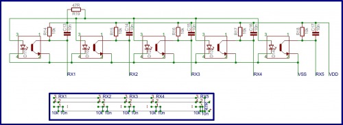
Scheme – reflective sensors:
PCB with reflective sensors:

Table of components – Reflective sensors:
Code | Type | Parameters | Function |
C13 – C17 | capacitor | ceramic 10 nF SMD 0805 | filtration of phototransistor output |
R14 – R18 | resistor | 10 kΩ | phototransistor output resistors |
R19 | resistor | 47 Ω | current limitations for LED diodes of reflective sensors |
RX1 – RX5 | reflective sensors | QRD1114 | track detection |
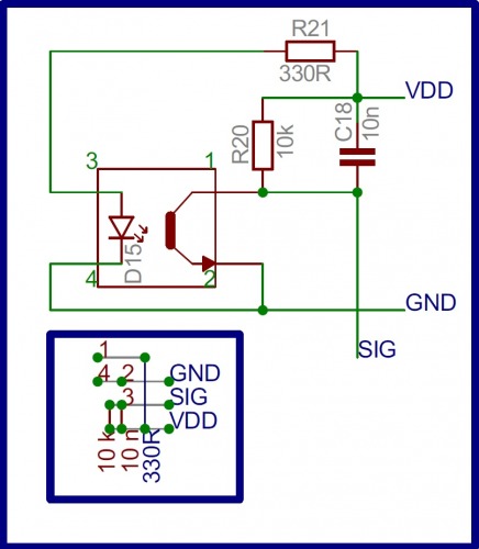
Scheme – back reflective sensor and encoder:
Table of components – back reflective sensor and encoder:
Code | Type | Parameters | Function |
C18 | capacitor | ceramic 10 nF SMD 0805 | phototransistor output filter |
R20 | resistor | 10 kΩ | phototransistor output resistor |
R21 | resistor | 330 Ω | current limitation for LED diode of the reflective sensor |
RX_BACK | reflective sensor | QRD1114 | home line detection or wheel encoder |
Wheel encoder:
Scheme - Battery pack:
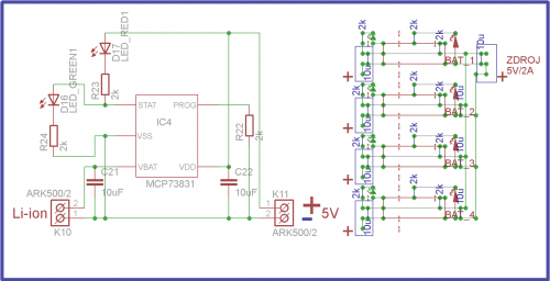
Battery pack – scheme of the switches connection:

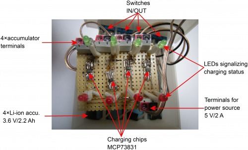
Table of components – Battery pack:
Code | Type | Parameters | Function |
C21 | capacitor | 4x ceramic 10 µF/25V SMD 1210 | charging chip output filtration |
C22 | capacitor | 4x ceramic 10 µF/25V SMD 1210 | charging chip filtration |
D16 | LED diode |
green indication LED 3 mm/ 2 mA | indication of charging status |
D17 | LED diode |
red indication LED 3 mm/ 2 mA | indication of charging status |
IC4 | integrated circuit | 4x MCP73831 | charging of a single-cell Li-ion battery |
K10 | terminal | 4x ARK500/2 | Li-ion accumulator connectors |
K11 | terminal | ARK500/2 | power source connector |
R22 | resistor | 2 kΩ | LED current limiting |
R23 | resistor | 2 kΩ | LED current limiting |
R24 | resistor | 2 kΩ | charging current selection |
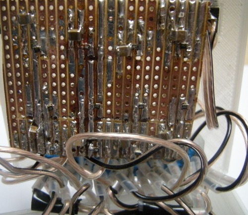
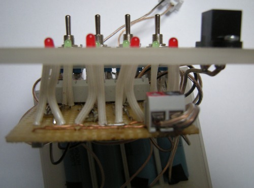
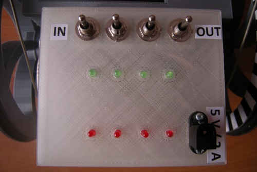
Battery pack photos:
3D models in SketchUp:
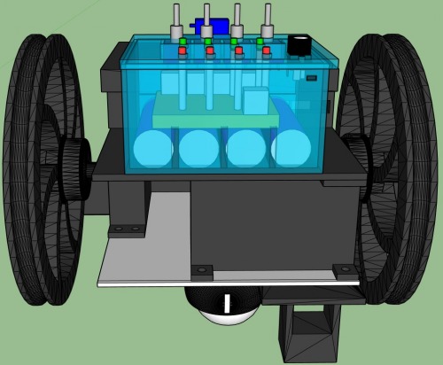
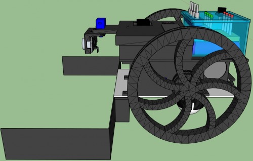
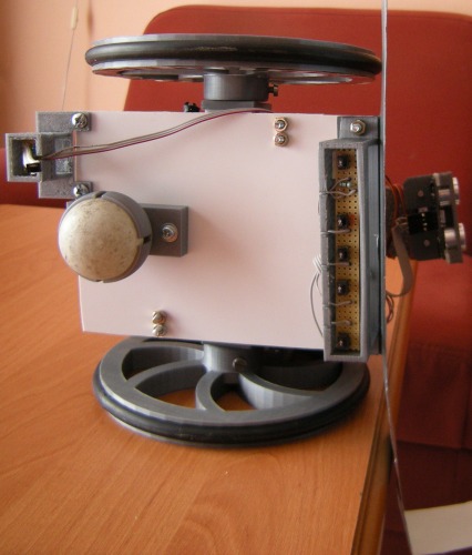
Photos of the robot:
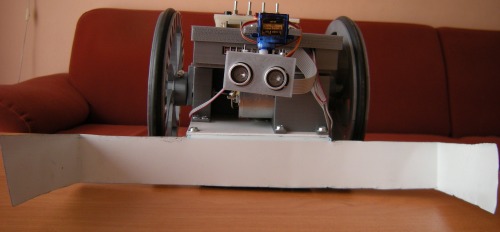
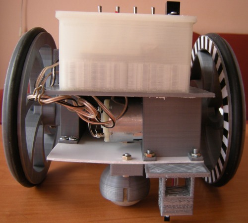
Motors:
A winning home-made robot for the Ketchup House competition at the Robotic Day 2016 in Prague.
- Actuators / output devices: speaker, 2x DC motors salvaged from HP Photosmart printer
- Control method: autonomous
- CPU: PIC16F1789
- Power source: battery pack 4x Li-ion 18650 2.2 Ah
- Programming language: C
- Sensors / input devices: HC-SR04 ultrasonic sensor
- Target environment: indoor
This is a companion discussion topic for the original entry at https://community.robotshop.com/robots/show/beda-6-a-robot-for-the-ketchup-house-competition


