BBF (Bigger, Better, Faster)

May 5, 2013 update

My robot has incrementally improved as I continued to learn what I could do with the arduino.  I followed a lot of your advise and removed all the delays from the main program, yet I still wanted more speed.  The local Microcenter store was having a sale on the arduino stuff, so I bought a second unit and connected it in tandem to the first using the I2C protocol.

I still have not used the infrared sensors as I found the range was too limited.  The master arduino carries the bluetooth shield and runs the main script.  It has 2 modes, MANual and AUTOmatic.  Manual mode simply makes the car an expensive RC toy, with all instructions coming from my Android phone via BT. The "microcontroller BT" app from KVNDEV in the Google Play Store was a perfect way to implement this mode.  It has a decent dynamic inerface for creating buttons and sliders. But with all this fun gear, I wanted more than just an RC car ;-)

The drive portion of the car came from China (of course):

http://www.ebay.com/itm/4WD-Robot-Smart-Car-Chassis-Kits-car-with-Speed-Encoder-DC-3v-5V-6V-for-Arduino-/180914530167?pt=LH_DefaultDomain_0&hash=item2a1f58a777

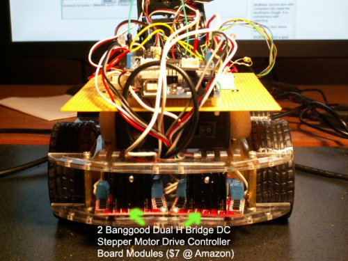
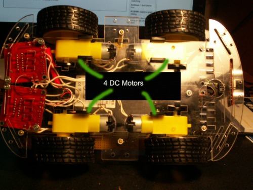
It came with 4 DC motors that I drive with 2 Banggood Dual H Bridge DC Stepper Motor Drive Controller Board Modules (L298N) bought from Amazon.  I can drive each motor independently if I want, but for now, I just drive each side.

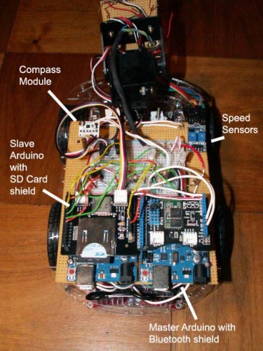
I have 4 optical speed sensors installed, but not connected.  I've found that the cheap tires/wheels tend to spin a lot, and measuring distance is a bit worthless with them.  Having cheap tires also caused the car to get stuck a lot as it traversed from wood to carpet, and I had to find a way to tell if a "turn" order had been completed, so I installed a compass module.  The first module I ordered was a Seeedstudio Grove 3-axis Digital Compass.  I had absolutely no luck with the unit - it would never show anything close to a zero-degrees no matter which way you pointed it.  I ended up ordering a Sainsmart unit ($15 cheaper) and it works great.

Since it's a bit of a pain to monitor both arduinos via serial port at the same time, I added the SD card shield to the slave arduino.  This also gives me the opportunity to log all the processes while it runs in auto mode, giving me some insight to what's going on when something goes wrong.  I have a "reset" button on my android that sets the speed to zero and closes the file on the SD card.

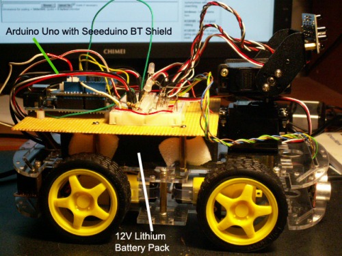
The big LED headlights were added after I was playing around with it in the near-dark.  The motor controllers already have a red LED, and they look like tail lights.

Front of car with BIG LED lights

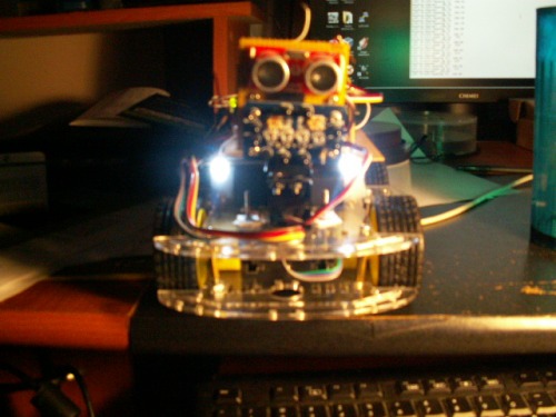
The following picture is the latest version with both arduinos mounted and compass module installed.

Here are older pics to show the motor drivers and battery location.

backside

bottom

It's been a fun ride so far.  I've learned a lot about coding, electronics, and I love working with the I2C stuff.

The code to run the car has been included.  Opinions and constructive criticizm would be appreciated.

Object avoidance via sonar, scares the cat

  • Actuators / output devices: 4 DC drive motors, 2 servos for pan/tilt
  • Control method: controlled by android phone via bluetooth (Microcontroller BT from Play Store)
  • CPU: 2x arduino unos
  • Operating system: C
  • Power source: 12V Battery
  • Sensors / input devices: DAGU IR Compound Eye, seeedstuido ultrasonic ranger finder, SainSmart HMC5883L Digital Compass Module
  • Target environment: indoor

This is a companion discussion topic for the original entry at https://community.robotshop.com/robots/show/bbf-bigger-better-faster

** **


Why use the mega??? Doesn’t

Why use the mega??? Doesn’t the atmega 328p have enough Memory/IOs?

It does for the time being…

But if I want to connect the compound IR, sonar, motor control, 2 servos, and speed control, I’ll be pushing it.  The compound IR itself is an analog IO pig.  I just need to be selective with each of my versions.  The car platform makes a great all-round stable base, even if I don’t want it to go anywhere ;-)  

Fortunately, DC power isn’t as big a problem.  The cheap motor controllers each offer regulated 5V to drive logic, sensors, and servos.

I see there is more than one

I see there is more than one with almost the same idea :slight_smile: my Stray will also have a lot of gear/gadgets. The choice of a Mega is good (strange, could not even find a word about the Mega) if you want to add some more.

Keep going and keep us updated :slight_smile:

Awesome - Great minds DO think alike! :wink:

I found this site just after I completed construction of my bot.  I did happen across your bot and had the same thought.

BBF has a new face

I scrounged around to find a basic obstacle avoidance sonar sketch, and most used servos, so I moved the sonar up and combined it with the compound IR.  I also added my seeedstudio bluetooth module.  I’ll upload my sketch to this site for others to use.  It’s real basic as far as obstacle avoidance is concerned, but it is pretty cool in that I can control in from my Android, and place it into manual mode to get it “unstuck”.  Once I get some more time, I’ll mess with the IR.

PICT0057.jpg

Some hard lessons learned so far:

1.  There is something different about ping 10.  I had to move my motor speed (PWM) to the motor controllers to a different DO to make it work at all.  I know that there are two ways to control speed thru controllers like mine - one thru the "HIGH" pin (set it to the speed you want, and the other LOW), or thru the "enable" pin, which seems to make more sense.  I've tried both, and stayed with the enable pin.  However, I have an intermittent issue with the motors just hanging while I hear a whine coming from the controllers.  If I reset the power, the issue goes away.  I have LEDs to monitor the status of the DO's and the only other time I get this whine is when the power to the speed pin is too low (not giving the motors enough juice).  I can see the DO's light properly, and the speedpin LED goes bright, but no response from the controllers other than the whine.

2.  The RxD and TxD pins on the Seeedstudio BT module are labeled backwards on the breadboard.  Thank you Google for helping me track that one down!

Please excuse to poor coding.  I haven't coded since I dd COBOL in the 80's!

The issue regarding that it

The issue regarding that it “stops” after a while could very well be due to brownouts. Try adding some 100uF polycarbonate capacitors on you power line. Put + on + and connect the negative side to ground. This will help with current spikes from the motors and what not.


What happens (just guessing, mind you) is that your motors or something else on your board draws too much current for a short time which makes one(or both) of your MCUs to reset due to the big current drop.

Regarding that it “stops” after a while

Gabriel,

Thanks for the input.  OddBot had it correct in that the code would halt for every little delay I wold place in the code, including serial output.  However, your idea to add the capacitor is also a great idea which I plan to incorporate just to smooth things out.

filmsmith