

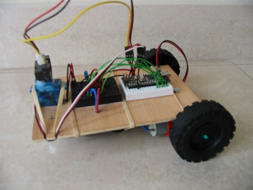
This is another attempt to build a "Start Here" clone. The photo is a prototype built with a reused mechanical & electrical platform.
I prefer Arduino for the brains because is open-source. Here I use an Arduino Nano for his small footprint but any other board can be used.
UPDATE (May 11th 2012):
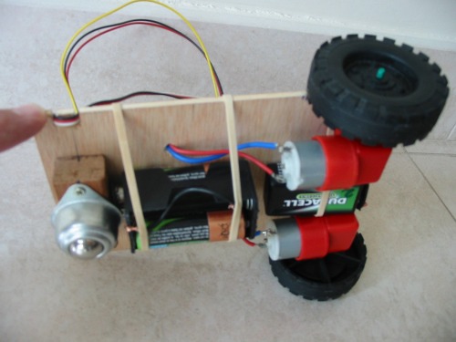
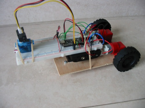
Platform trimmed down, and wheels advanced.
Now the performance is better. The motors' batteries now are between them and then the wheels don't slip in the turns. The weight is better balanced.
I've had to adjust the program because now the angle of the turns was excessive.
UPDATE (May 5th 2012):
Worn gear replaced
Video added.
I'm thinking in another change in the platform: The robot is too long respect its width, and finds it difficult to turn. It has sharp corners that make it hook somewhere. I'm thinking in a round base with the wheels inside the perimeter.
UPDATE (April 15th 2012):
Remodeled platform:
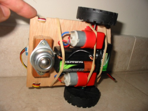
I've substitued the large breadboard for two small ones, flipped the base with the motors and changed the battery positions.
Now the motors and the batteries are under the base and the circuit and sensor are above. The batteries and the servo are held with rubber bands.
In the photo above you can see a 4 AA battery holder with only 3 batteries. I have problems with the number of batteries for the motors: 2 batteries give not enough voltage to turn the motors, but 4 batteries make the robot runs so fast that when the sensor detects that must stop, the robot almost crashes into walls. Three fully charged batteries are not bad but when depleted can hardly drag the robot.
I've to add flyback diodes to the outputs of the H-bridges to test if the motors stop immediately when the outputs of the bridges are at low level.
I started thinking about using four batteries, and with an analog input, measure the voltage provided in order to apply a PWM to reduce proportionally the voltage applied to the motors. But it's only one idea at the moment.
Another problem is that a worm gear has started to wear. I have to find a replacement part.
Reprogrammed sketch:
As I've commented in the first version, the wheels slip when start to rotate. Then I've added two small functions that performs a simple PWM to control the start of the motors in 10 steps for an adjustable period (variable "time"). The "AnalogWrite" standard function of Arduino can not be used because of the SN754410NE. The functions are soft_start_mono and soft_start_dual. At this time only soft_start_mono is used, specifically in turn_left and turn right.
Arduino code:
// Arduino Start Here LMR Version 2
// Antoni Ubieto
#include <Servo.h>
Servo servo; // create servo object to control a servo
int pos = 0; // variable to store the servo position
int distance_dangerous = 200; // 35 .. 40 cm
int distance_ahead;
int pinSensor = A0;
void setup()
{
servo.attach(8); // attaches the servo on pin 8 to the servo object
servo.write(90); // looks forward
delay (200); // waits servo turn
// four H-bridge SN754410NE
// always enabled -> 1,2EN & 3,4EN connected to high level
// motor 1: pins 9 & 10 (outputs 1A i 2A)
// motor 2: pins 11 & 12 (outputs 3A i 4A)
pinMode(9, OUTPUT);
pinMode(10, OUTPUT);
pinMode(11, OUTPUT);
pinMode(12, OUTPUT);
// Serial.begin(9600);
}
void soft_start_mono(int time, int pin)
{
int t = time/100;
for (int s = 1; s < 11; s++)
{
digitalWrite(pin, LOW);
delay((10-s)*t);
digitalWrite(pin, HIGH);
delay(s*t);
}
}
void soft_start_dual(int time, int pin1, int pin2)
{
int t = time/100;
for (int s = 1; s < 11; s++)
{
digitalWrite(pin1, LOW);
digitalWrite(pin2, LOW);
delay((10-s)*t);
digitalWrite(pin1, HIGH);
digitalWrite(pin2, HIGH);
delay(s*t);
}
}
void robot_stop()
{
// Serial.println("STOP");
// motor 1 stop
digitalWrite(9, LOW);
digitalWrite(10, LOW);
// motor 2 stop
digitalWrite(11, LOW);
digitalWrite(12, LOW);
}
void robot_forward()
{
// Serial.println("FORWARD");
// motor 1
digitalWrite(9, HIGH);
digitalWrite(10, LOW);
// motor 2
digitalWrite(11, HIGH);
digitalWrite(12, LOW);
}
void turn_left()
{
// Serial.println("LEFT");
// motor 1 stop
digitalWrite(9, LOW);
digitalWrite(10, LOW);
//motor 2 forward
digitalWrite(12, LOW);
// digitalWrite(11, HIGH);
soft_start_mono(800, 11);
// delay (600); //adjust!!!!
digitalWrite(11, LOW);
digitalWrite(12, LOW);
}
void turn_right()
{
// Serial.println("RIGHT");
//motor 2 stop
digitalWrite(11, LOW);
digitalWrite(12, LOW);
// motor 1 forward
digitalWrite(10, LOW);
// digitalWrite(9, HIGH);
soft_start_mono(800, 9);
// delay (600); //adjust!!!!
digitalWrite(9, LOW);
digitalWrite(10, LOW);
}
int distance_left()
{
servo.write(20); // from 90º to 20º:looks to the left
delay (200);
int dist_left = analogRead(pinSensor); //note the distance
servo.write(90); //back to 90º
delay (200);
return dist_left;
}
int distance_right()
{
servo.write(160); // from 90º to 160º:looks to the right
delay (200);
int dist_right = analogRead (pinSensor); //note the distance
servo.write(90); // back to 90º
delay (200);
return dist_right;
}
void loop()
{
distance_ahead = analogRead (pinSensor);
// Serial.println("distance ahead");
// Serial.println(distance_ahead);
// delay (1000);
if (distance_ahead > distance_dangerous)
{
robot_stop();
if (distance_right() > distance_left()) turn_left(); else turn_right();
}
else robot_forward();
}
********************************
FIRST VERSION:
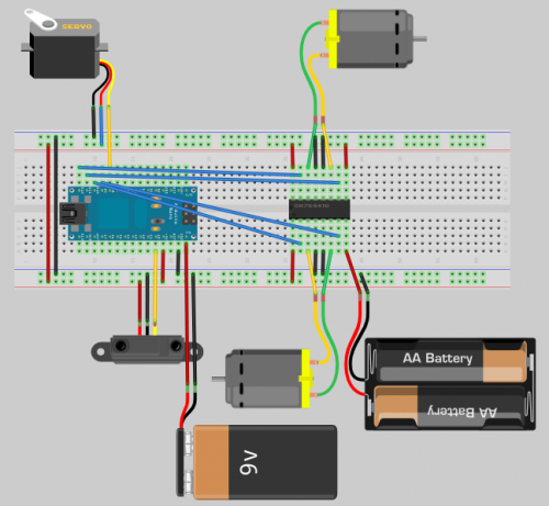
A SN754410NE (quadruple half-H driver) is used to drive the two wheels' motors. It can drive currents of 1A maximum, but I measured the stall current of these motors and is over 2A at 4V (stabilised power supply). The IC is thermally protected, and I expect that the internal resistance of the four AA rechargeable NiMH batteries helps to survive the chip. The starting torque is impressive, the rubber wheels slip when starting. I'll seriously consider using PWM.
Below you can see the connections in the Fritzing Breadboard view (zip compressed file):
And here the Arduino code:
Notes:
- The Shap sensor output a bigger voltage when distance is lesser.
- The angle of rotation at right and left is not controlled. In practice it may be adjusted changing the delay in functions turn_left() and turn_right().
- There are some debugging points commented out, which prints information in the Arduino IDE Serial Monitor. They are useful when you want to test the direction of rotation of the motors in the different functions, with the wheels rotating in the air.
****************************************************************************
// Arduino Start Here LMR Version 1
// Antoni Ubieto
#include <Servo.h>
Servo servo; // create servo object to control a servo
int pos = 90; // variable to store the servo position
int distance_dangerous = 150; // about 50cm
int distance_ahead;
int pinSensor = A0;
void setup()
{
servo.attach(8); // attaches the servo on pin 8 to the servo object
// quadruple half-H bridge SN754410NE
// always enabled -> 1,2EN & 3,4EN connected to high level
// motor 1: pins 9 & 10 (outputs 1A i 2A)
// motor 2: pins 11 & 12 (outputs 3A i 4A)
pinMode(9, OUTPUT);
pinMode(10, OUTPUT);
pinMode(11, OUTPUT);
pinMode(12, OUTPUT);
// Serial.begin(9600);
}
void robot_stop()
{
// Serial.println("STOP");
// motor 1 stop
digitalWrite(9, LOW);
digitalWrite(10, LOW);
// motor 2 stop
digitalWrite(11, LOW);
digitalWrite(12, LOW);
}
void robot_forward()
{
// Serial.println("FORWARD");
// motor 1 forward
digitalWrite(9, HIGH);
digitalWrite(10, LOW);
// motor 2 forward
digitalWrite(11, HIGH);
digitalWrite(12, LOW);
}
void turn_left()
{
// Serial.println("LEFT");
// motor 1 stop
digitalWrite(9, LOW);
digitalWrite(10, LOW);
// motor 2 forward
digitalWrite(11, HIGH);
digitalWrite(12, LOW);
delay (600); //adjust!!!!
// motor 2 stop
digitalWrite(11, LOW);
digitalWrite(12, LOW);
}
void turn_right()
{
// Serial.println("RIGHT");
// motor 1 forward
digitalWrite(9, HIGH);
digitalWrite(10, LOW);
// motor 2 stop
digitalWrite(11, LOW);
digitalWrite(12, LOW);
delay (600); //adjust!!!!
// motor 1 stop
digitalWrite(9, LOW);
digitalWrite(10, LOW);
}
int distance_left()
{
servo.write(20); // from 90º to 20º:looks to the left
delay (200);
int dist_left = analogRead(pinSensor); // note the distance
servo.write(90); //back to 90º
delay (200);
return dist_left;
}
int distance_right()
{
servo.write(160); // from 90º to 160º:looks to the right
delay (200);
int dist_right = analogRead (pinSensor); // note the distance
servo.write(90); // back to 90º
delay (200);
return dist_right;
}
void loop()
{
servo.write(90); // looks forward
delay (200);
distance_ahead = analogRead (pinSensor);
// Serial.println("distance ahead");
// Serial.println(distance_ahead);
// delay (1000);
if (distance_ahead > distance_dangerous) // bigger distance lesser output from sensor!!!
{
robot_stop();
if (distance_right() > distance_left()) turn_left(); else turn_right();
}
else robot_forward();
}
************************************************************************************
Navigate around via infrared distance sensor
- Actuators / output devices: 2x worm screw gear motors
- CPU: atmega168
- Power source: 1x 9V for microcontroller and 3 x AA for motors
- Sensors / input devices: Sharp GP2Y0A21 F IR sensor
- Target environment: indoor
This is a companion discussion topic for the original entry at https://community.robotshop.com/robots/show/arduino-version-of-lmr-start-here