555 Timer Photovore Robot

This is a simple robot that I made for my cousin, it only uses 2 LDRs, 2 geared motors, and a 555 timer IC.

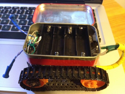
I reused a Tamiya Tank tread kit and gearbox for locomotion. All powered by 4 AA batteries. The batteries, IC, and switch are all housed in an Altoids tin.

Not much more to say about this robot (Sorry OddBot) 

Requested pictures: 

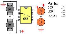
Schematic I found from the internet.

There's not much to see on the inside because i DeadBugged the 555 Timer.


EDIT: As of July 25, 2012 this robot no longer belongs to me. It has been shipped off to Chicago to give company to my cousin.

Searches for light

  • Actuators / output devices: Tamiya twin gearbox with treads
  • Power source: 4x AA
  • Sensors / input devices: 2 photoresistors

This is a companion discussion topic for the original entry at https://community.robotshop.com/robots/show/555-timer-photovore-robot

RC time constant?

I think, if I got the schematic right in my head, you’re using two 555 timers in astable mode to generate the motor PWM and the LDRs vary the RC time constant to change the pulsewidth of the motor PWM.

Am I right? :stuck_out_tongue:

nope

I’m using a much simpler method. One 555 timer, two dc motors, not servos. a voltage divider output from the ldrs is fed into the 555 timer. I’ll post a schematic soon.

Yeah I was thinking of two

Yeah I was thinking of two geared DC motors but only one 555? Now I’m interested in the schematic :slight_smile:

Anyway nice and simplistic and it does it’s job

Nice

Nice

Yep, we need schematics,

Yep, we need schematics, video, a look inside the “box”. There is so much ti say about this robot… :slight_smile: (need a purpose to dig out my 555’s)

can that robot work with 3

can that robot work with 3 AA batteries??

I have found

That 4 rechageble AAs won’t work well if their voltage is too low. The motors seem to run fine, but the light seeking behaviour is impaired. I wouldn’t recommend 3 AAs

i am planing to build

i am planing to build something like that only much much smaller


Very cool!

Thanks for posting the schematic. 

I tried it last night and

I tried it last night and it’s working. However, we started with 3.7V but it needs a bit more juice. Best running with 6V.

Now we got another simple line follower, with a 555…cool.


Good Luck!

Remember to use high geared motors because this robot takes shallow turns, so a slow moving robot will perform better, that was the only real problem I had. I would also use a potentiometer in parallel of the LDRs to trim the sensors if needed.

Yes, we used small gear

Yes, we used small gear motors but no pot for the testing. 

Well, that’s a good

Well, that’s a good decision, so you need to build another companion for yourself :wink:

great concept! I like it

great concept! I like it alot…

Thanks.

This was my first robot I ever made. 

**I like it! **

Same circuit as in the Hivebugs! I love this BEAM design, its a great beginner project and tons of fun to make.

Nice

Simplicity is bliss


Schematic?

Is this the correct way to attach the potentiometer? (Ignore the switches in the begining :wink: )

|x


Photodiodes

The photodiodes replace LDRs (needed IR not “White Light”)