

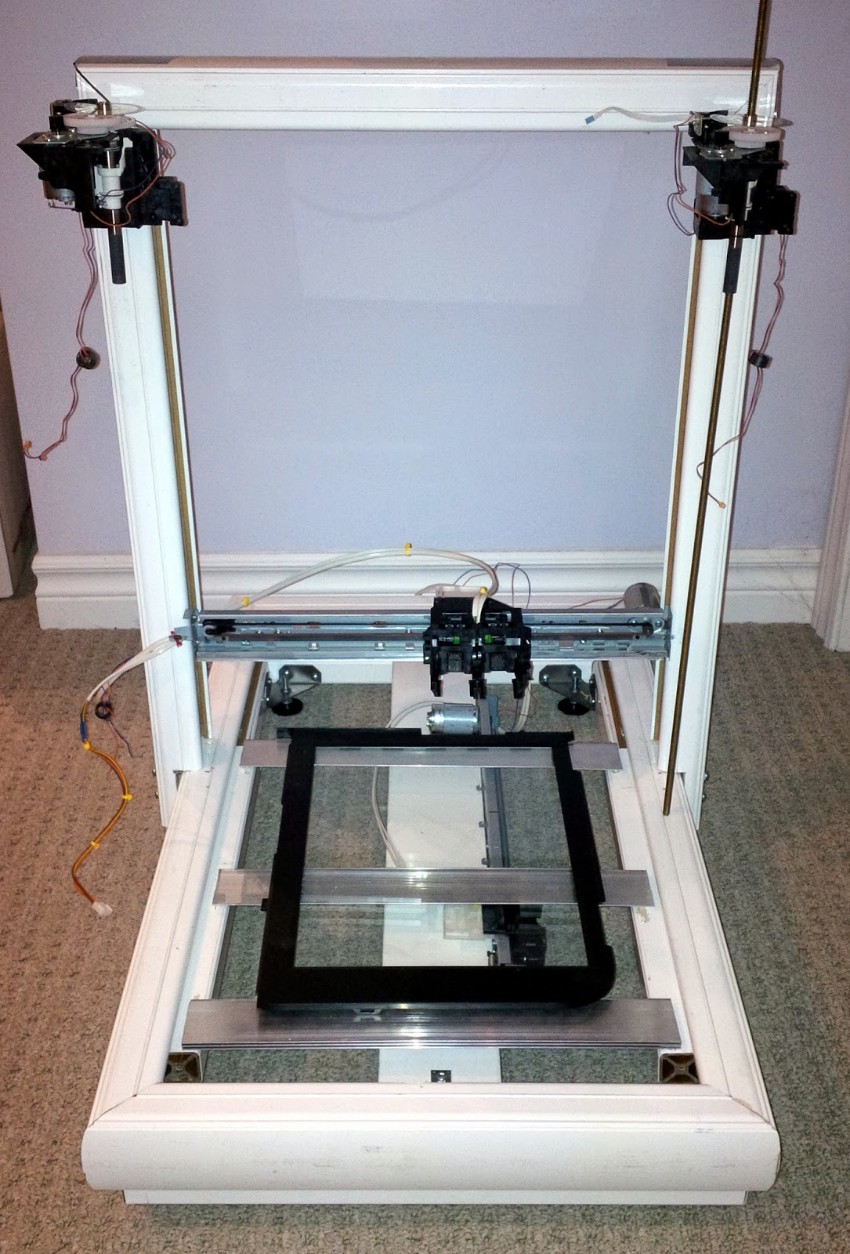
Using the Arduino PID Library for precise position control of X and Y axis on RepScrap printer

I've updated the test code I'm using to manage my X and Y axis DC motor / linear encoder closed loop controller.

I am currently using the Arduino PID Library by Brett Beauregard for this, and having great success.
(Videos to come tomorrow.)
I am *NOT* going to explain what PID is, or how PID works.... I couldn't possibly do it justice. I'll simply point you to Brett's wonderful explanation:
In the following example, I set up two axis, X and Y, each using a DC motor run from the Adafruit Motor Shield V2. This shield provides PWM control for up to four separate DC motors via I2C communications.
I then set up two Quadrature encoders, one for each axis, using the Hardware Interrupts 0 and 1 (Arduino digital pins 2 and 3) and high speed digital port reads for one half of each encoder, and then validate the state of the other phase pin of the encoder during the interrupt routine:
Graciously borrowed from http://forum.arduino.cc/index.php?topic=41615.20;wap2
The ZERO endstop for each axis is set up using the Arduino PinChangeInterrupt library watching a pin attached to a photo-interrupter.
I would certainly accept any advice on a proper sequence to initialize each axis to the ZERO endstop.
Right now, I arbitrarily send the carriage forward for 100ms assuming this is enough time to get on the positive side of the endstop, if we were beyond it. Then I set my current position to the maximum possible location, and start travelling back to the endstop, knowing that once I actually reach it, the interrupt routine will Zero out my position, and initialize my PID setpoint to zero as well, thus stopping travel at ZERO.
Is there a more efficient way of doing this?
Inside the loop portion of my code, I run the PID controls as per the library, providing motor speed control via the Adafruit motor class, and periodically check to see if both X and Y axis have reached their goal. At which time, I randomly select a new target for each. When I get to the real application of this, the random selection of X and Y axis targets will be replaced by GRBL coordinates.
And without further ado, here is my working code for precise position control in X and Y axis using the Arduino PID library:
/***************************************************************************************
* Lin_Enc_02.ino 05-12-2014 unix_guru at hotmail.com @unix_guru on twitter
* http://arduino-pi.blogspot.com
*
* This sketch allows you to run two salvaged printer carriages for X/Y axis using their
* linear encoder strips for tracking.
* This example uses the Arduino PID Library found at:
* https://github.com/br3ttb/Arduino-PID-Library/archive/master.zip
*
* Hardware Interrupt 0 on Digital pin2 is used to determine X-Axis position
* Hardware Interrupt 1 on Digital pin3 is used to determine Y-Axis position
* PinchangeInterrupt is used to identify the Zero Endstop for X and Y axis
*****************************************************************************************/
#include <Wire.h>
#include <Adafruit_MotorShield.h>
#include "utility/Adafruit_PWMServoDriver.h"
#include <PID_v1.h>
#include <PinChangeInt.h>
#define frontstop = 100 // Right most encoder boundary
#define backstop = 3600 // Left most encoder boundary
// Create the motor shield object with the default I2C address
Adafruit_MotorShield AFMS = Adafruit_MotorShield();
// Select which 'port' M1, M2, M3 or M4. In this case, M1
Adafruit_DCMotor *XaxisMotor = AFMS.getMotor(1);
Adafruit_DCMotor *YaxisMotor = AFMS.getMotor(2);
const int XaxisENCPinA = 2; // X-AXIS encoder 1 on pins 2 and 4
const int XaxisENCPinB = 4;
const int XaxisENDSTOP = 10; // Endstop photointerrupter for X-Axis
volatile double XaxisENCPos = 0;
const int YaxisENCPinA = 3; // Y-AXIS encoder 2 on pins 3 and 5
const int YaxisENCPinB = 5;
const int YaxisENDSTOP = 11; // Endstop photointerrupter for Y-Axis
volatile double YaxisENCPos = 0;
double XaxisSpd, YaxisSpd; // Carriage speed from 0-255
double XaxisPos, YaxisPos; // Current Carriage position
/*working variables for PID routines*/
// Tuning parameters
float KpX=0, KpY=0; //Initial Proportional Gain
float KiX=10, KiY=10; //Initial Integral Gain
float KdX=0, KdY=0; //Initial Differential Gain
double XaxisSetpoint, YaxisSetpoint; // Taget position for carriage
// Instantiate X and Y axis PID controls
PID XaxisPID(&XaxisPos, &XaxisSpd, &XaxisSetpoint, KpX, KiX, KdX, DIRECT);
PID YaxisPID(&YaxisPos, &YaxisSpd, &YaxisSetpoint, KpY, KiY, KdY, DIRECT);
const int sampleRate = 1;
long int reportTime;
void setup() {
Serial.begin(115200);
Serial.println("Linear Encoder Test 05-12-2014");
AFMS.begin(); // Set up Motors
XaxisMotor->run(BACKWARD); // Bring carriage to home position.
XaxisMotor->setSpeed(70);
delay(100); // Get endstop limiter working here
XaxisMotor->run(FORWARD); // Bring carriage to home position.
XaxisMotor->setSpeed(0);
attachInterrupt(0, doXaxisENC, CHANGE); // encoder pin on interrupt 0 (pin 2)
attachInterrupt(1, doYaxisENC, CHANGE); // encoder pin on interrupt 1 (pin 3)
PCintPort::attachInterrupt(XaxisENDSTOP,doXaxisEndstop,FALLING); //X-axis Endstop ISR
PCintPort::attachInterrupt(YaxisENDSTOP,doYaxisEndstop,FALLING); //Y-axis Endstop ISR
randomSeed(analogRead(0)); // Used to select random setpoints for testing
XaxisPID.SetMode(AUTOMATIC); //Turn on the PID loop
XaxisPID.SetSampleTime(sampleRate); //Sets the sample rate
YaxisPID.SetMode(AUTOMATIC); //Turn on the PID loop
YaxisPID.SetSampleTime(sampleRate); //Sets the sample rate
reportTime = millis()+2000;
}
void loop() {
uint8_t oldSREG = SREG; // Store interrupt status register
cli();
XaxisPos = XaxisENCPos;
YaxisPos = YaxisENCPos;
SREG = oldSREG; // Restore interrupt status register
// Temporary to create random X and Y axis setpoints for testing
if(millis() > reportTime) { // Only validate this every 2 seconds
if(XaxisPos == XaxisSetpoint && YaxisPos == YaxisSetpoint) {
// If both X-axis and Y-axis have reached their target - get new targets
XaxisSetpoint = random(200,3500); // Keep target within bounds of Endpoints
YaxisSetpoint = random(200,3500); // Keep target within bounds of Endpoints
}
}
// Manage X-axis positioning
XaxisPID.Compute(); //Run the PID loop
if(XaxisSetpoint < XaxisPos) XaxisMotor->run(BACKWARD); // Determine direction of travel
else XaxisMotor->run(FORWARD);
XaxisMotor->setSpeed(XaxisSpd); // Apply PID speed to motor
// Manage Y-axis positioning
YaxisPID.Compute(); //Run the PID loop
if(YaxisSetpoint < YaxisPos) YaxisMotor->run(BACKWARD); // Determine direction of travel
else YaxisMotor->run(FORWARD);
YaxisMotor->setSpeed(YaxisSpd); // Apply PID speed to motor
}
/***************************************************************************************
The following code was taken from http://forum.arduino.cc/index.php?topic=41615.20;wap2
to utilize the fast port based encoder logic. Thank you Lefty!
please go there for a full explanation of how this works. I have truncated the comments
here for brevity.
***************************************************************************************/
void doXaxisENC() { // ************** X- AXIS ****************
if (PIND & 0x04) { // test for a low-to-high interrupt on channel A,
if ( !(PIND & 0x10)) { // check channel B for which way encoder turned,
XaxisENCPos = ++XaxisENCPos; // CW rotation
PORTD = PIND | 0x40; // set direction output pin to 1 = forward,
}
else {
XaxisENCPos = --XaxisENCPos; // CCW rotation
PORTD =PIND & 0xBF; // Set direction output pin to 0 = reverse,
}
}
else { // it was a high-to-low interrupt on channel A
if (PIND & 0x10) { // check channel B for which way encoder turned,
XaxisENCPos = ++XaxisENCPos; // CW rotation
PORTD = PIND | 0x40; // Set direction output pin to 1 = forward,
}
else {
XaxisENCPos = --XaxisENCPos; // CCW rotation
PORTD =PIND & 0xBF; // Set direction output pin to 0 = reverse,
}
}
PORTD = PIND | 0x80; // digitalWrite(encoderstep, HIGH); generate step pulse high
PORTD = PIND | 0x80; // digitalWrite(encoderstep, HIGH); add a small delay
PORTD = PIND & 0x7F; // digitalWrite(encoderstep, LOW); reset step pulse
} // End of interrupt code for encoder #1
void doYaxisENC(){ // ************** X- AXIS ****************
if (PIND & 0x08) { // test for a low-to-high interrupt on channel A,
if (!(PIND & 0x20)) { // check channel B for which way encoder turned,
YaxisENCPos = ++YaxisENCPos; // CW rotation
PORTB = PINB | 0x01; // Set direction output pin to 1 = forward,
}
else {
YaxisENCPos = --YaxisENCPos; // CCW rotation
PORTD =PIND & 0xFE; // Set direction output pin to 0 = reverse,
}
}
else { // it was a high-to-low interrupt on channel A
if (PIND & 0x20) { // check channel B for which way encoder turned,
YaxisENCPos = ++YaxisENCPos; // CW rotation
PORTB = PINB | 0x01; // Set direction output pin to 1 = forward,
}
else {
YaxisENCPos = --YaxisENCPos; // CCW rotation
PORTB =PINB & 0xFE; // Set direction output pin to 0 = reverse,
}
}
PORTB = PINB | 0x02; // digitalWrite(YaxisENCstep, HIGH); generate step pulse high
PORTB = PINB | 0x02; // digitalWrite(YaxisENCstep, HIGH); used to add a small delay
PORTB = PINB & 0xFD; // digitalWrite(YaxisENCstep, LOW); reset step pulse
} // End of interrupt code for encoder #2
void doXaxisEndstop() {
XaxisENCPos=0; // X-Axis Endstop indicates ZERO position
}
void doYaxisEndstop() {
YaxisENCPos=0; // Y-Axis Endstop indicates ZERO position
}
https://github.com/michaeljball/RepScrap
References:
DIYDrones: Tutorial series for new Arduino PID library
http://brettbeauregard.com/blog/2011/04/improving-the-beginners-pid-introduction/
Tim Wescott's PID without a PHD
http://abigmagnet.blogspot.ca/2008/10/dc-motor-control-part-one.html
http://www.pdx.edu/nanogroup/sites/www.pdx.edu.nanogroup/files/2013_Arduino%20PID%20Lab_0.pdf
https://www.youtube.com/watch?v=ZZYgZjMnGXU
https://www.youtube.com/watch?v=wbmEUi2p-nA
http://blog.solutions-cubed.com/pid-motor-control-with-an-arduino/
http://forum.arduino.cc/index.php/topic,45169.0.html
http://playground.arduino.cc/Code/PIDLibrary
http://playground.arduino.cc/Code/PIDAutotuneLibrary
Arduino Playground: PinChangeInterrupt Library
https://code.google.com/p/arduino-pinchangeint/downloads/list
LetsMakeRobots: PID Control by Big Face
LetsMakeRobots: PID Tutorials for Line Following by Enigmerald
LetsMakeRobots: PID without a PHD by BDK6
LetsMakeRobots: Using Motor Encoders to Control Speed by Oddbot
Thanks for helping to keep our community civil!
This post is an advertisement, or vandalism. It is not useful or relevant to the current topic.
You flagged this as spam. Undo flag.Flag Post
Your post is currently under review by our moderation team. The review process usually takes up to 48 business hours.
You can track your post's status in the "My Content" section of your profile. Once approved, it will be published and visible to others.

Thank you for contributing to our community!