Robot Reverse Engineering: Designing an Autonomous Transatlantic Boat

Some of you may have hear about Scout -- The Autonomous Transatlantic Robot. She is a 12-foot long robotic solar-powered boat designed and built by 7 college/university students from the USA. She was launched in August 2013 from Rhode Island and programmed to autonomously cross the Atlantic Ocean to her destination in Spain. Although she did complete more than 1300 miles autonomously, radio contact was lost in November and she is presumed to have sunk.
[caption id="attachment_12865" align="aligncenter" width="500"]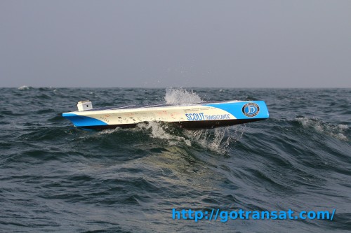 Scout — The Autonomous Transatlantic Robot[/caption]
Although the trip was unsuccessful, the project is far from a failure: they set a new record for the longest distance traveled by an autonomous boat, they were featured in prominent media including IEEE, MAKE, and others, and they have founded their own companies and now do consulting work on similar industrial projects.
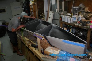 Scout Under Construction[/caption]
For the rudder, we would choose a 12V high torque servo, such as the Torxis. We know that the Torxis servos have a Jrk 21v3 motor controller in them which run off of 5-28V, so that means that this motor is also good to be connected directly to the battery without a regulator. We would also choose this motor because it is heavy duty, with all metal gears and designed for continuous operation. In fact, early in Scout's trip, the servo motor for the rudder did burn out and had to be replaced. From the pictures on their Facebook page, its does seem like they had used a standard hobby servo, which are usually only design to run about 20% of the time.
Since the Iridium 9612 transceiver radio is also made to run off of a 12V car battery, it would not need a power regulator either. However, since it uses an RS-232 serial port for communication, we would need an adapter to convert the signals to TTL for use with the Arduinos.
Finally, there's the electronic. While the Arduino Megas do have their own voltage regulators, a 12V battery -- which has a voltage of ~13V when charging/charged -- is at the upper end of the recommended input range. Since we will also be using other 5V devices, we would choose to use a separate 5V regulator module to power our electronics.
[caption id="attachment_12891" align="aligncenter" width="300"]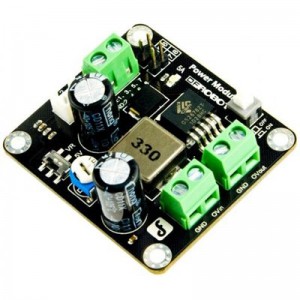 DC-DC Power Converter 25W[/caption]
 Scout — The Autonomous Transatlantic Robot[/caption]
Although the trip was unsuccessful, the project is far from a failure: they set a new record for the longest distance traveled by an autonomous boat, they were featured in prominent media including IEEE, MAKE, and others, and they have founded their own companies and now do consulting work on similar industrial projects.
Vehicle Design
But how do you make such a robot? Their site already has a great Build Page that chronicles the process of building the vehicle mechanics. [caption id="attachment_12913" align="aligncenter" width="300"] Scout Under Construction[/caption]
Electronics
There isn't a lot of information available about the electronics. These are the specifications we do know:- Scout is a solar-powered electric boat that has a trolling motor (permanent position).
- Scout has an adjustable rudder controlled by a servo.
- Scout uses two Arduino Mega microcontrollers; one to handle navigation, and one to handle sensors and communication
- Scout has an Iridium 9612 transceiver for reporting her telemetry once per hour for remote monitoring.
Power
First thing: power. We know that the boat is solar powered, so that would mean we need large solar panels, a solar charger module, and a large 12V deep-cycle lead acid battery. This part of system is probably one of the simplest: if there's sun, the charger module will charge the battery. There seems to be four things that consume power on the boat: the main trolling motor, the rudder's servo, the Iridium radio, and the main electronics. The main motor is likely made to run off of a 6-18V power source, so all we need is a DC motor controller, like a Sabertooth, to connect the motor to the battery.
[caption id="attachment_12885" align="aligncenter" width="300"]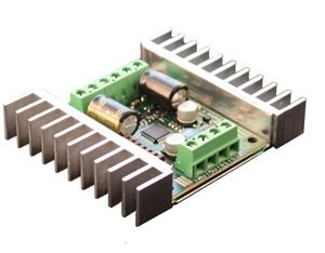 Sabertooth Dual 12A Motor Controller[/caption] Sabertooth Dual 12A Motor Controller[/caption]
|
[caption id="attachment_12886" align="aligncenter" width="300"]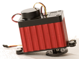 Torxis i00800 High Torque Servo Motor[/caption] Torxis i00800 High Torque Servo Motor[/caption]
|
 DC-DC Power Converter 25W[/caption]
Control Logic
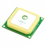
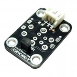
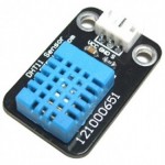
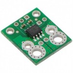
The control logic is the trickier part. We know that Scout has one Arduino Megas to handle the navigation, and another to handle sensors and communication. The first Arduino must be connected to a GPS module so that we can know the location, surface speed, and heading (course over ground) of the boat. This Arduino also needs to be provided with a list of waypoints that mark the path from Rhode Island to Spain. These waypoints can either be directly programmed into the code, or provided through an SD card. The main Arduino is then programmed to use the telemetry data from the GPS and the waypoint information to determine the desired heading and calculate the R/C PWM signal necessary to move the rudder to the angle necessary to point the boat in that direction. The second Arduino is in charge of sensors and communication. There is very little information about the sensors used on Scout, so here is a list of sensors we would include:- temperature sensors to measure the ambient temperature, the internal temperature, and the battery temperature,
- humidity sensors to measure for condensation and leaks,
- electric current sensors to measure the current consumption of the main motor and the servo motor, to try to anticipate any problems such as seaweeds getting attached,
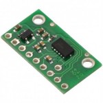
- accelerometers to measure the rocking of the boat,
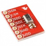
- pressure sensor to monitor the weather,
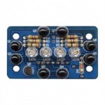
- infrared sensors to measure the ambient light,
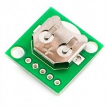
- a real time clock to keep track of the current time,
- and finally a simple voltage divider circuit to measure the battery voltage.
Thanks for helping to keep our community civil!
Notify staff privately
You flagged this as spam. Undo flag.Flag Post
It's Spam
This post is an advertisement, or vandalism. It is not useful or relevant to the current topic.
This post is an advertisement, or vandalism. It is not useful or relevant to the current topic.
You flagged this as spam. Undo flag.Flag Post


