

R/C with arduino & NRF24L01+ 2.4GHz Antenna Wireless Transceiver Module


October, 11th 2012
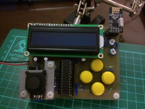
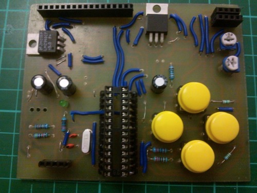
Well, my prototype remote controller is nearly finished now.
Bellow you can see the ON/OFF switch placement (that's for you Hoff).

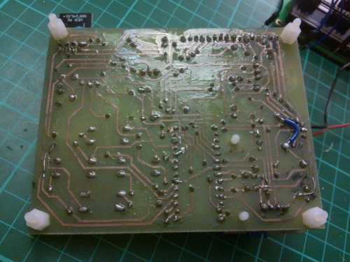
The backside of the board after a hand of nail polish (yeah, I know, yet another archaic method). Also notice the little blue jumper wire that I had to add to correct Eagle's auto-routing mistake (and my blindness to detect it at the that time).
Also I spent a lot of time unsoldering the female header I've previously had soldered into the LCD... it was not easy... at all, I would say 1-2 hours just to unsolder and clean 16 points. But then I could solder in the needed male headers.
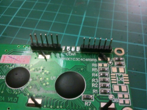
And, voilá... now I only need to deal with the power supply attachment, and connection (waiting on JST connectors).
October, 9th 2012
So, since last time time I've been busy doing multiple iterations of the PCB design and last Sunday ended up with etching this one:
heat toner tranfer ... (in the 'soaking tub' with a side board for the mouse bot project)

etched them (and cleaned the toner off)
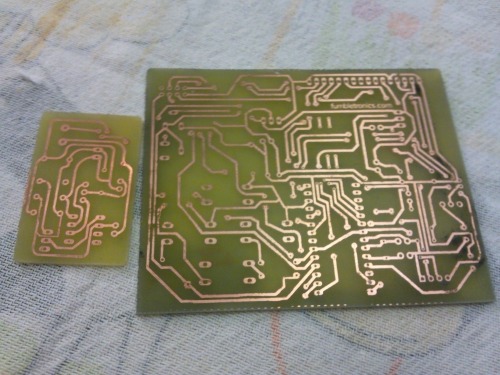
the process went along reasonly well, just a couple of tracks ended up broken (which I later solder fix them).
And them (mostly) hand-drill them given that without a drill press accessory my dremel-like Einhell tool is not so easy to control :| believe me, I've tried.... hence the slanted IC socket on the little board below...
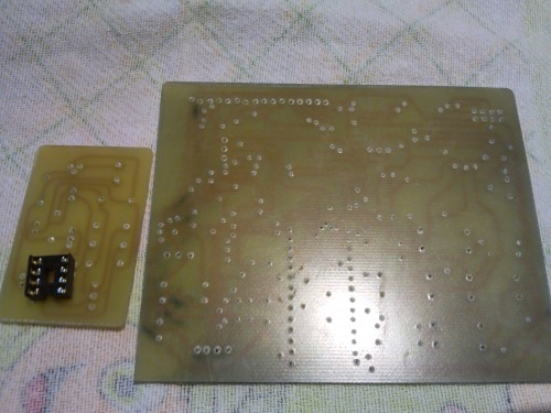
I was then starting to arrange the jumper wires for the top surface when I noticed something... I had used a WIDE 28DIP socket on my design instead of a NARROW socket, which would fit much better a 28dip atmega... OH WHY OH WHY??? Ok, after a few moments of self-name calling... I got cranking... and on the next day I came up with this:
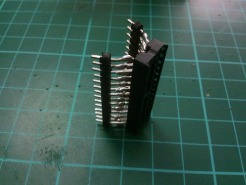
Easy fix, if albeit somewhat ugly... I call it the "centipede"... or better yet, the "tetradecapede" IC socket.
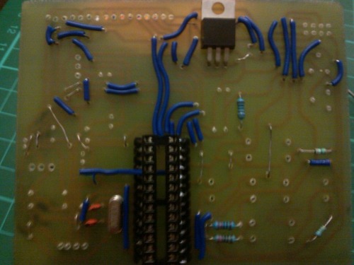
...and then came more soldering... *sigh* and not sure why (bad quality, poor caretaking?) my soldering tip made me solder even worse than my usual shoddy soldering jobs... there seems to be oxidation (rust) aplenty on the solder tip... and it's hard to make the "tinning stick" and I've been careful to often tin the tip since from the moment I started using it. I haven't even used this tip to poke holes on plastic... *sigh* anyhow... lo and behold... crappy... I know...

Soldering a lot of jumper wires... is TIME CONSUMING.... given all the time spent cutting wires to length, crimmping them, placing them, holding them in place and then actually soldering and cutting off any leads when required.
Half-way through on the front side it was looking like this:
...and by middle of the night... it was near completed (solder-wise):
September, 21th 2012
Well amidst many distractions, duties and extremelly delayed parcels from China I've been slowly working on my prototype "chipped stone" transmitter for RC future robotic creations.
Basically I've only tested one LCD 16x2, a setup with voltage divider for measuring a LiPo voltage (intend to power remote with it). Also found the pinout of a PSP 2000 thumbstick and drafted a partial-tentative circuit for the remote using EagleCAD. For radio I will use NRF24L01+ 2.4GHz Antenna Wireless Transceiver Modules, I've already got a couple of them while another one with PA and external aerial waits for inspection in Customs. (another 4 standard ones are on the way).

Since I'm going to use the parallel interface for the LCD, hence I've already reserved:
LCD: Digital Pins 2, 3, 4, 5, 7 and 8
I know I could use a SPI/I2C converter, but I only have one and did not want to use it up just now, plus I still haven't found a DIY SPI/I2C converter for these LCDs (today during my search I found candidate options, I'll be getting a needed IC so that I can test my favourite).
- for the nRF24L01+ module I've reserved pins:
Digital Pins 9, 10, 11, 12 and 13
for the Thumbstick I can use, for instance:
Analogue Pins: A0, A1
and for the battery voltage checking:
Analogue Pin: A5
So, I'm left with 3 Analogue pins (A2, A3 & A4)
and
3 Digital Pins (0, 1 & 6)
and having some buttons in my remote would be nice I guess. My concerns? well I've read this:
"""
SERIAL COMMUNICATION
Used for communication between the Arduino board and a computer or other devices. All Arduino
boards have at least one serial port (also known as a UART or USART). It communicates on digital
pins 0 (RX) and 1 (TX) as well as with the computer via USB. Thus, if you use these functions, you
cannot also use pins 0 and 1 for digital input or output.
on http://arduino.cc/en/Tutorial/AnalogInputPins also left me somewhat wary about the possible practical implications.
Can somebody provide some ease of mind? practial experience regarding my concerns?
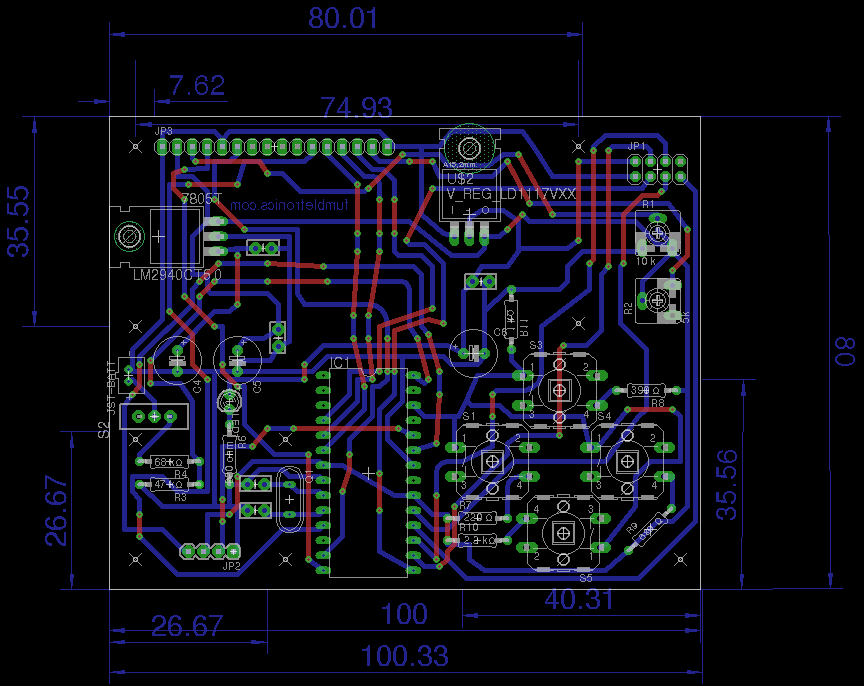
Also, below is posted my provisional schematic for the circuit ready to receive comments:

Original Post
Ok, I think it's about time I start delving into the Radio Controled business. Initially I though I would just canabilize a rc toy and hack it's parts, and also use one of R/C transmitters I have at home (2.4GHz & 25MHz). However, the 2.4GHz is for my micro heli and I don't have any intentions of disposing of it seeing that it still flies (even after so much abuse :p). The other (35Mhz) is a micro r/c I wouldn't mind scraping that, however the car is too tiny, and the circuit-wire mashup inside does not appear very appealing.
Hence I've decided to do something from scratch even more so after seeing these entries:
https://www.robotshop.com/letsmakerobots/node/27952
by Rasoul. The schematics are very nice and I could probably replicate the circuits, however it uses teh RFM12 modules and I couldn't find any cheap enough for my liking...
...also I already bought a couple of NRF24L01+ that costed only USD $4. Furthermore I'm more at ease using 2.4GHz because I know it's allowed by law around here, provided I don't go above some value I don't quite recall but I reckon it's enough for my range of control (around my small apartment).
then I found out that Badji have already been fiddling with these things just before I joined LMR
https://www.robotshop.com/letsmakerobots/node/31410
Keep in mind I'm interested only on the Tx/Rx part of the project. So far I've only skimmed through the project, but I think I'll be more specific details, so Badji, if you read this expect on being badgered by me :P If you're not reading this... then you're in for quite a surprise :P
------
Original post text at the main project page -- moved here -- for aesthetic reasons
--- Initial post ---
(...)
Project Objectives:
- Build controlable vehicle from scratch (more on that around-mid August) -- NOT currently open for discussion!
- Built/implement RC system around the NRF24L01+ 2.4GHz Antenna Wireless Transceiver Modules
--- This includes building a customized Transmitter to pair with a customized Receiver module.
AS OF THE MOMENT I'll accept tips regarding the Tx - Rx circuitry building part ONLY!
Thanks for helping to keep our community civil!
This post is an advertisement, or vandalism. It is not useful or relevant to the current topic.
You flagged this as spam. Undo flag.Flag Post
Your post is currently under review by our moderation team. The review process usually takes up to 48 business hours.
You can track your post's status in the "My Content" section of your profile. Once approved, it will be published and visible to others.

Thank you for contributing to our community!