

"How to": Modular, Mobile IoT Hardware

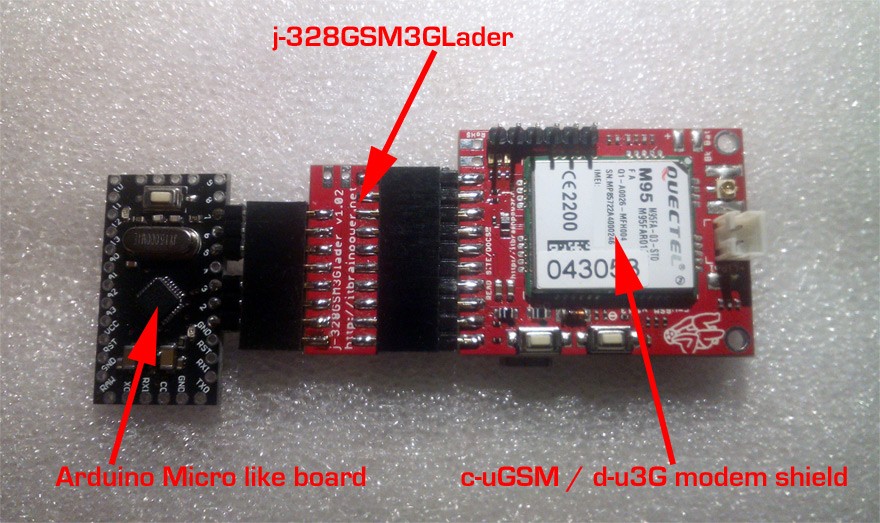
The main purpose of this "how-to" article it is to guide you on how to make a convenient and elegant modular GSM or 3G hardware platform using an Arduino Pro Mini (and related) board, a j-328GSM3GLader Arduino Pro Mini adapter board and c-uGSM / d-u3G / h-nanoGSM modem shields. The purpose of a programmable GSM interface is to be able to communicate with electronics / hardware directly via the cellular network (SIM card required), without the need for a cell phone. You may use such a platform as a mobile IoT interface (access sensor data remotely, or control actuators) or as an SMS / GPRS / DTMF automation platform.
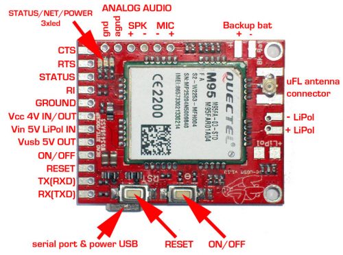 c-uGSM - dual sim modular gsm modem
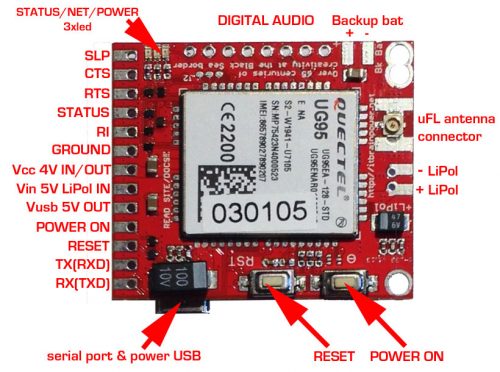 d-u3G - modular 3G modem
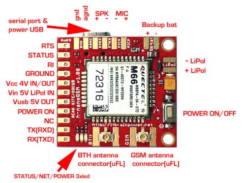
h-nanoGSM - modular GSM modem
The h-nanoGSM has the same functionality as its bigger brothers (c-uGSM and d-u3G), and is not only a breakout board, but a full shield with powerful embedded features including USB support (communication and powering), auto power level 2.8V-5V digital interfaces and an integrated LiPo battery charger.
 j-328GSM3GLader PCB top and bottom
In the pictures above, note that the GSM/3G and the 328 microcontroller chip markings on the BOTTOM face, as well as the solder jumpers (placed on the BOTTOM face):
j-328GSM3GLader PCB top and bottom
In the pictures above, note that the GSM/3G and the 328 microcontroller chip markings on the BOTTOM face, as well as the solder jumpers (placed on the BOTTOM face):
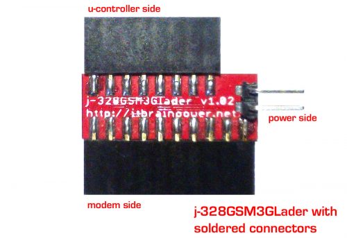 j-328gsm3glader with connectors soldered
a. Select the 1x10 pin 2.54mm (0.1") header received with the j-328GSM3GLader bundle.
b. Solder it into the modem side of the j-328GSM3GLader PCB. Soldering to the large pads (top face) is recommended instead of using through-hole.
c. Select the 1x8 pin 2.54mm (0.1") header received with the j-328GSM3GLader bundle.
d. Solder it into the microcontroller side (marked as "328" on the PCB) of the j-328GSM3GLader PCB.
e. Solder one 1x2 pin 2.54mm (0.1") pheader into the power side (optional) of the j-328GSM3GLader PCB (90 degree header shown above).
f. Check for short-circuits.
j-328gsm3glader with connectors soldered
a. Select the 1x10 pin 2.54mm (0.1") header received with the j-328GSM3GLader bundle.
b. Solder it into the modem side of the j-328GSM3GLader PCB. Soldering to the large pads (top face) is recommended instead of using through-hole.
c. Select the 1x8 pin 2.54mm (0.1") header received with the j-328GSM3GLader bundle.
d. Solder it into the microcontroller side (marked as "328" on the PCB) of the j-328GSM3GLader PCB.
e. Solder one 1x2 pin 2.54mm (0.1") pheader into the power side (optional) of the j-328GSM3GLader PCB (90 degree header shown above).
f. Check for short-circuits.
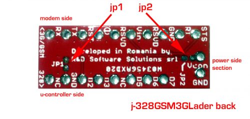 j-328GSM3GLader JP1, JP2 - reference
Use the image above as reference:
j-328GSM3GLader JP1, JP2 - reference
Use the image above as reference:
 "Export" Vcc (modem's +4V in/out)
 modular mobile IoT hardware assembled
Case 2: Connection between the Arduino Pro Mini, 3G or GSM modular modem and g-SPS switching power supply
modular mobile IoT hardware assembled
Case 2: Connection between the Arduino Pro Mini, 3G or GSM modular modem and g-SPS switching power supply
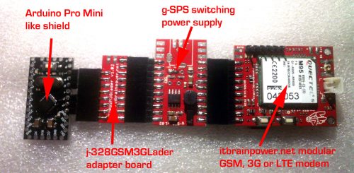 modular mobile IoT assembled, including switching power supply
Case 3: Power the Arduino Pro Mini from the same power source
The idea is to use an external 5V power supply to power the modem (ex: use g-SPS 5V source + Lithium Polymer battery or direct 5V power as "Power config b" or "Power config c" described earlier). If your Arduino Pro Mini (like) board is rated for 5V, the only thing to do is to solder one wire from the j-328GSM3GLader +5V PAD (marked as Vin) to the Arduino Pro Mini +5V IN (usually marked as Vcc - check your board documentation!). The second case is the same as above, but your Arduino Pro Mini is instead rated at 3.3V. The solution would be the same as above, but connect to the Arduino Pro Mini's RAW pad! An alternative is to connect using one 1N4148 diode, in direct polarization, to the MODEM VCC +4V pad [or corresponding j-328GSM3GLader PAD] to the Arduino Pro Mini +3V3 IN (usually marked as Vcc - check your board and other electronics inter-connected documentation!). Warning: the voltage that powers the Arduino Pro Mini will provide around 3.2-3.4V, but may very widely! The same approach can be used as in second case and applied for the "Power config a" and using Arduino Pro Mini 5V version. Instead of an 1N4148 diode, use one plain wire (we've tested several Mega328p/16V down to 3.2V and even lower @ room temperature). In conclusion, always read first and solder later, and double check what you are doing! The j-328GSM3GLader and itbrainpower.net modular modems offer support for multiple powering schemes and (almost) endless hacking.
modular mobile IoT assembled, including switching power supply
Case 3: Power the Arduino Pro Mini from the same power source
The idea is to use an external 5V power supply to power the modem (ex: use g-SPS 5V source + Lithium Polymer battery or direct 5V power as "Power config b" or "Power config c" described earlier). If your Arduino Pro Mini (like) board is rated for 5V, the only thing to do is to solder one wire from the j-328GSM3GLader +5V PAD (marked as Vin) to the Arduino Pro Mini +5V IN (usually marked as Vcc - check your board documentation!). The second case is the same as above, but your Arduino Pro Mini is instead rated at 3.3V. The solution would be the same as above, but connect to the Arduino Pro Mini's RAW pad! An alternative is to connect using one 1N4148 diode, in direct polarization, to the MODEM VCC +4V pad [or corresponding j-328GSM3GLader PAD] to the Arduino Pro Mini +3V3 IN (usually marked as Vcc - check your board and other electronics inter-connected documentation!). Warning: the voltage that powers the Arduino Pro Mini will provide around 3.2-3.4V, but may very widely! The same approach can be used as in second case and applied for the "Power config a" and using Arduino Pro Mini 5V version. Instead of an 1N4148 diode, use one plain wire (we've tested several Mega328p/16V down to 3.2V and even lower @ room temperature). In conclusion, always read first and solder later, and double check what you are doing! The j-328GSM3GLader and itbrainpower.net modular modems offer support for multiple powering schemes and (almost) endless hacking.
What you will need:
- 1x GSM modules:
- c-uGSM shield (micro) v1.13. or
- d-u3G shield (micro) v1.13 (European and International version / USA and Americas version) or
- h-nanoGSM shield (micro) v1.08
- 1x switching power supply:
- g-SPS v1.02, switching power supply 4V [DDRV] version or
- 5V [LiPOL] version 1 pcs (not mandatory, but can be a interesting solution for certain configuration).
- 1x Adapter: j-328GSM3GLader Arduino Pro Mini adapter board v1.02(*)
- 1x Arduino Pro Mini (or similar) board:
- Pro Mini 3.3V / 8MHz Arduino Compatible Microcontroller or,
- DFRduino Pro Mini 5V Microcontroller or,
- Arduino Mini 05 Microcontroller Module or,
- Arduino Mini 05 Microcontroller Module or,
- other compatible module (Arduino Micro, Arduino Nano USB, ArduinoPro Mini, Atmega32U4 based Fio board, Arduino Yun Mini)***
- 1x Optional 2x 0.1" (2.54mm) straight or 90 degree standard pin header
- Soldering iron & solder, cutter, pliers, wire.
Hardware conventions and references
GSM Module
The c-uGSM and d-U3G shields are pin to pin compatible with each other. The c-uGSM is quad band (worldwide compatible) and has support for 2x SIM cards. The other unit uses a single 3G SIM (model d-u3G = North American version; 3G+GSM = Europe and rest of the world; h-nanoGSM = quad band GSM only and is worldwide compatible) + Bluetooth 3.0 nano shield, packed in an compact format 1.25"x1.16"(31.75x29.46mm) and weighs around 8g.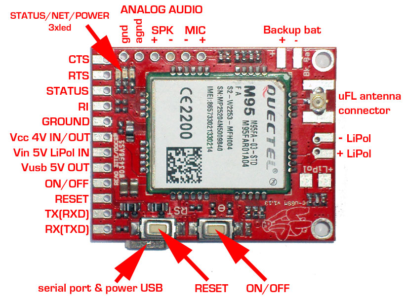 c-uGSM - dual sim modular gsm modem
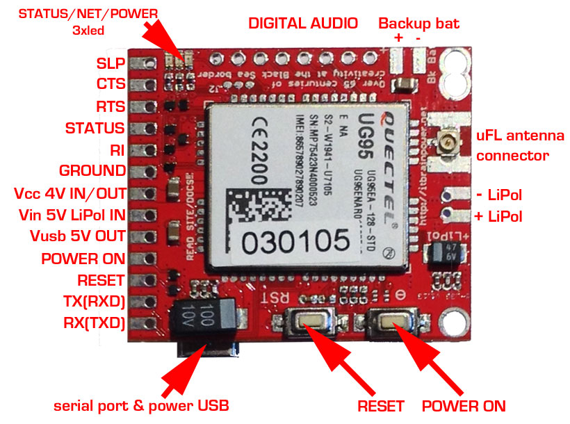 d-u3G - modular 3G modem
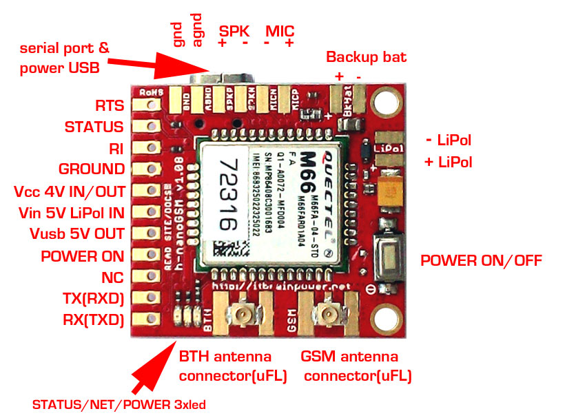
h-nanoGSM - modular GSM modem
Switching Power Supplies
Both the g-SPS 4V [DDRV] and g-SPS 5V [LiPOL] switching power supplies mentioned in the parts list are modular, designed for pin to pin compatibility with itbrainpower.net's family of modems. The first one (g-SPS 1.02 - 4V [DDRV]) is used as power supply adapter for the c-uGSM / d-u3G / h-nanoGSM shields in configurations without a Lithium Polymer battery. The second one (g-SPS 1.02 - 5V [LiPOL]) is used in configurations with a Lithium Polymer battery connected to the shield, when the main power source has a voltage above 5V (6-18V).Arduino Pro Mini Adapter
To make the long story short, the j-GSM3GLAder adapter allows you to directly connect the Arduino Pro Mini (like) boards with itbrainpower.net modular GSM / 3G or (near future) LTE modem shields. This saves considerable wiring and saves the designer the time of having to fully inderstand each circuit.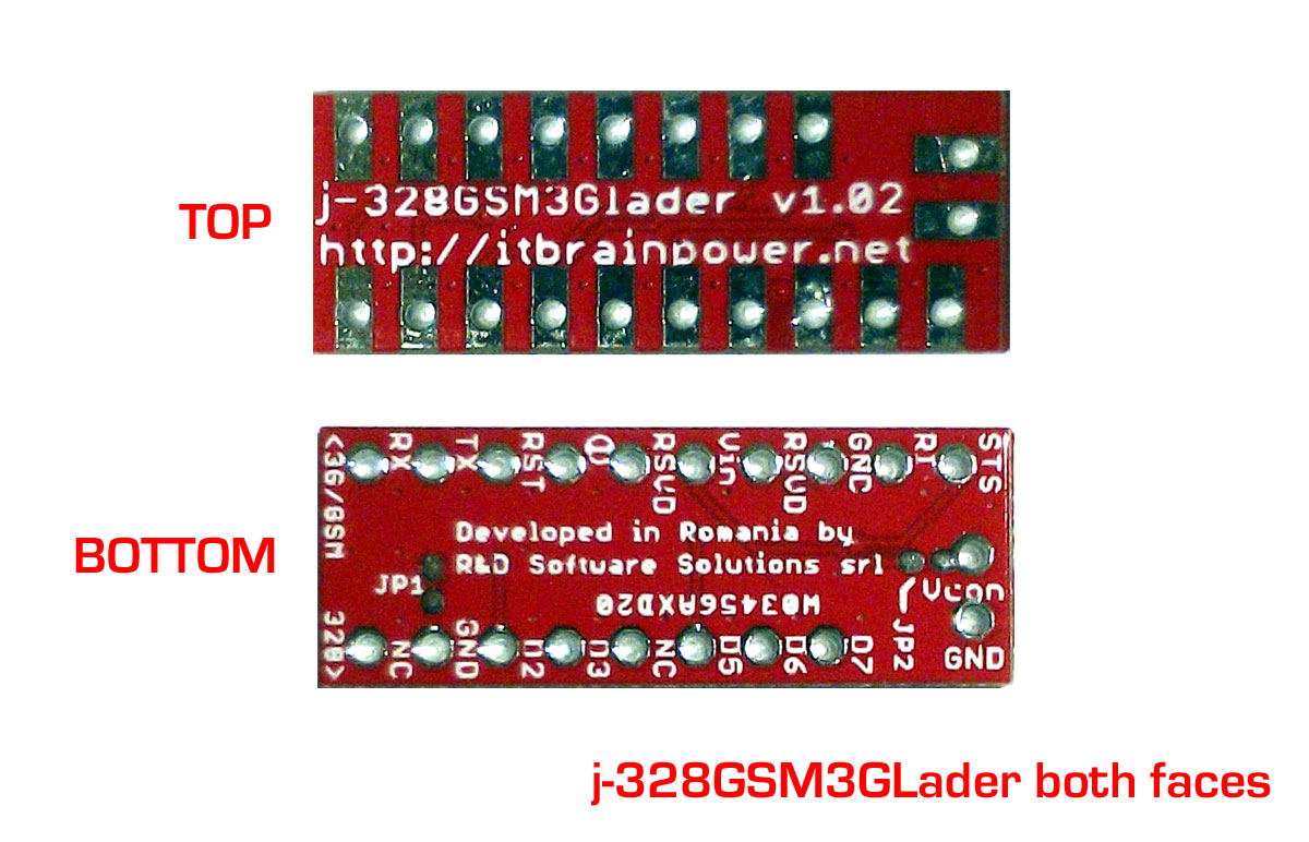 j-328GSM3GLader PCB top and bottom
- JP1 - GND : The circuit is CLOSED (connected) by default, so WATCH OUT: when a microcontroller with no GND is used, read the "NO GND workaround" below.
- JP2: the circuit between Vcon POWER on "POWER SIDE SECTION" and Vin (5V on GSM/3G connector) is OPEN (not connected) by default.
Hardware connections
Solder Connectors
Solder the connectors to the top and bottom of the adapter, as in the picture below. The boards design gives you the possibility for various connectivity options. Here, we present the "single plane (2D) variant".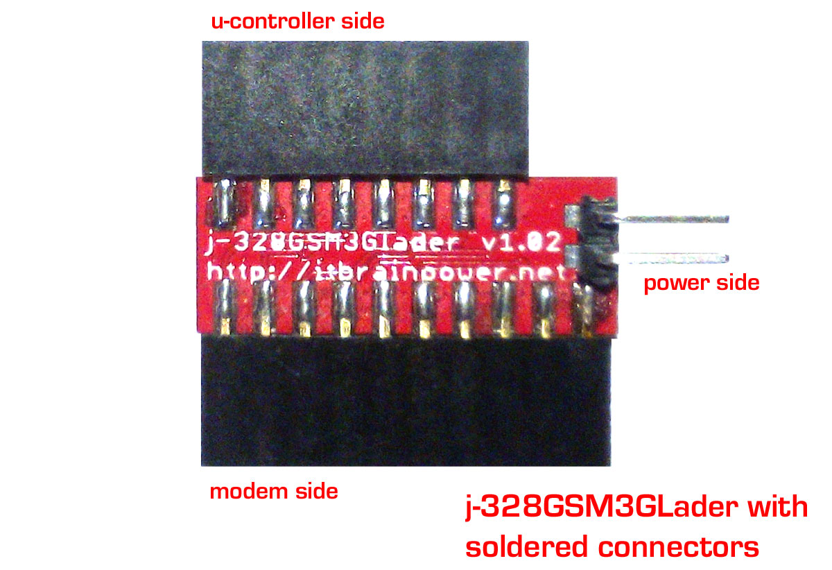 j-328gsm3glader with connectors soldered
Hardware Configuration & Power Options
Check the hardware reference for your microcontroller and identify the following pins: GND, D2, D3, D4, D5, D6 and D7 (D4 may not be used). If GND is missing (examples of such boards include: a-star mini, Metro Mini 328, Pro Trinket...), then read below for the "No GND workaround" solution), otherwise leave JP1 as is (DEFAULT circuit closed - connected). Solder some 2.54mm (0.1") pin headers into the Ardruino Pro Mini pinholes identified before. For this ("single plane / 2D") variant, use 90 degrees pin headers. j-328GSM3GLader JP1, JP2 - reference
- Power config a: Modem is not powered externally (runs on LiPOL battery only) > leave JP1 as is (DEFAULT circuit open - not connected). Connect the Lithium Polymer battery to the modem. This way, the modem's onboard Lithium Polymer charger it is not powered and not used.
- Power config b: Power the modem via two pins on the "Power side" (Vcon) connector > make a short on the solder jumper JP1. On Vcon you may supply +5V. The modems will be used with a Lithium Polymer battery connected. This way, the modem's Lithium Polymer onboard charger it is powered and used.
- Power config c: Power the modem via the modem's USB connector > make a solder short between the LEFT RSVD (placed between I/O and Vin pads) pad and the Vin pad; make a short on the solder jumper JP1 ONLY if you want to export Vusb via Vcon pad ("Power side section") . On Vcon you may supply +5V. Modems will be used with the Lithium Polymer battery connected. This way, the modem's Lithium Polymer charger it is powered and used.
Hacks
Power options are not limited at the ones presented above, however: BE SURE YOU KNOW WHAT ARE YOU DOING BEFORE MAKING CHANGES!"No GND workaround"
Using a cutting tool / exacto knife, carefully cut the GND trace between the two pads of the solder-jumper JP1 so the two no longer connect to each other. Solder one wire (after you plug the boards together) between the j-Lader GND pad and one GND pinhole/area placed on the Arduino Pro Mini board.Route the Vcc (modem's +4V in/out) via "Power side section"
Leave JP2 unsoldered (open circuit), and solder a small wire between the right pad of the JP2 (or Vcon pad) and the RIGHT RSVD pad: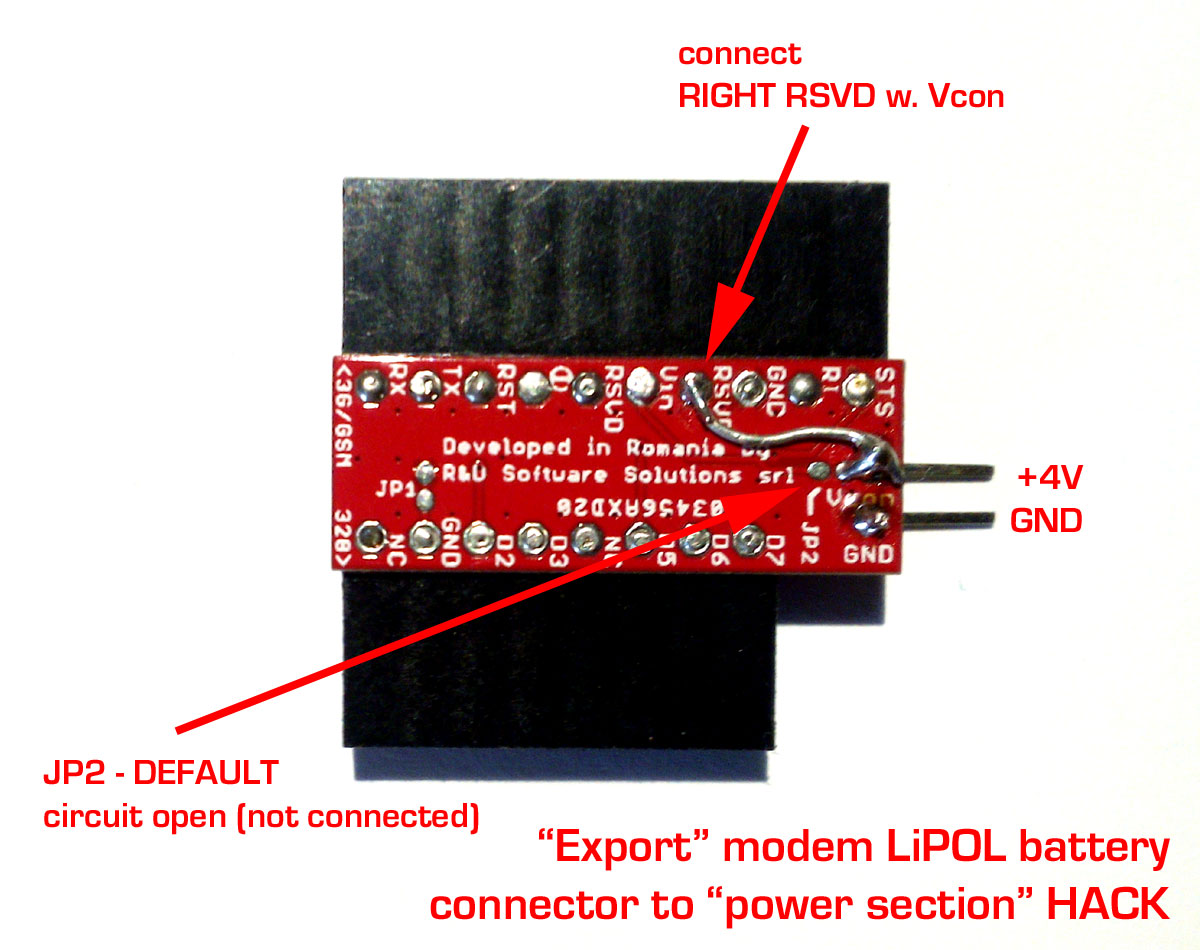 "Export" Vcc (modem's +4V in/out)
Connecting the Boards
Keep in mind when you connect/plug the boards: a. j-Lader to Arduino Pro Mini alignment can be done having D7 as a reference pin b. modem to j-Lader alignment: both boards start with RX Case 1: Straight connection between the Arduino Pro Mini and 3G or GSM modular modem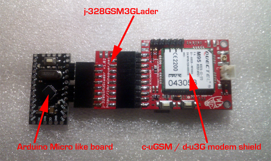 modular mobile IoT hardware assembled
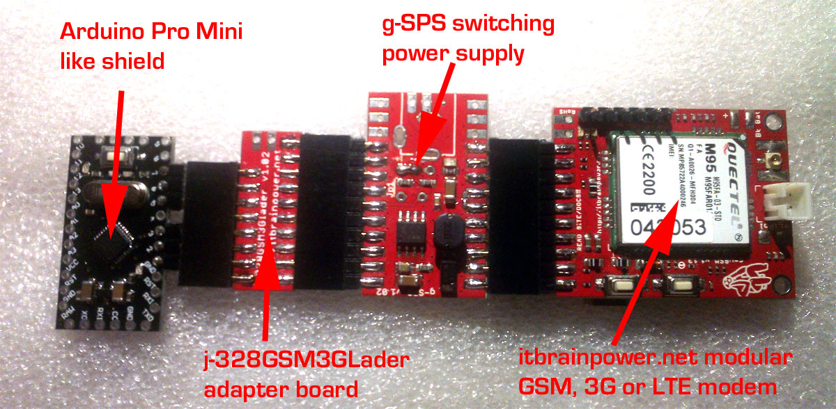 modular mobile IoT assembled, including switching power supply
Connecting sensors and actuators
On the Arduino Pro Mini board there are additional IO available for connecting sensors and actuators. D4, D8->D13 digital pins and A0->A3 analog pins are unused and free to use however you want. Just adapt your project / code in order to use those interfaces for sensors and actuators to complete your specific project.Software configuration
All ARDUINO software support examples are available in the DOWNLOAD section, as of August 2016, and supports the j-328GSM3GLader Arduino Pro Mini adapter board. You can even download an Arduino GSM class hack that allows you to run (almost) any project written for Arduino GSM shields which use itbrainpower.net's modular GSM (c-uGSM or h-nanoGSM) modems. All you need to do is to remove the comment for the "#define usejLader" compiling directive (or to add this directive) in the software example. For older software versions, you may define the connectivity as follows (regardless of if you use c-uGSM, d-u3G or h-nanoGSM modular shields):- RX => D3
- TX => D2
- POWERON => D7
- RESET => D6
- STATUS => D5
Thanks for helping to keep our community civil!
Notify staff privately
You flagged this as spam. Undo flag.Flag Post
It's Spam
This post is an advertisement, or vandalism. It is not useful or relevant to the current topic.
Report Reason
This post is an advertisement, or vandalism. It is not useful or relevant to the current topic.
You flagged this as spam. Undo flag.Flag Post
✅ Your Post Has Been Submitted Successfully!
Your post is currently under review by our moderation team. The review process usually takes up to 48 business hours.
You can track your post's status in the "My Content" section of your profile. Once approved, it will be published and visible to others.

Thank you for contributing to our community!