

How To Enable Active GNSS Antenna On LTE 4G Shield


itbrainpower.net l-LTE v1.07 4G/LTE CAT 1 shield and l-LTE v 1.07 4G/LTE CAT 4 shield, the smallest 4G/LTE shields available today, have one high-performance GNSS [GPS+GLONASS] engine embedded. By default, the GNSS antenna circuitry is configured for passive antennas [does not have enabled the GNSS antenna power supply circuitry]. Even if the performances achieved with passive GNSS [GPS+GLONASS] antennas are quite impressive, for some projects the usage of active GNSS antenna it's a must.
Bellow, you can find how to enable the active antenna powering circuitry for the l-LTE shields.
Platforms: ARDUINO, BEAGLEBONE, TEENSY, RASPBERRY PI or other 2.8V-5V micro-controller or SBC.
Time needed: maximum 10 minutes.
Previous skills required: Soldering.
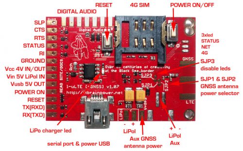 l-LTE LTE/4G + GNSS shield - top details
In the image up here, notice:
a. the "SJP1 and SJP2 - GNSS antenna power selector" solder jumpers. By default, both SJP1 and SJP2 are in "CIRCUIT OPEN" configuration [no connection between solder jumpers pads].
b. the "Aux GNSS antenna power" pad [marked "v+GPS" on the board]- variant for the GNSS antenna power source.
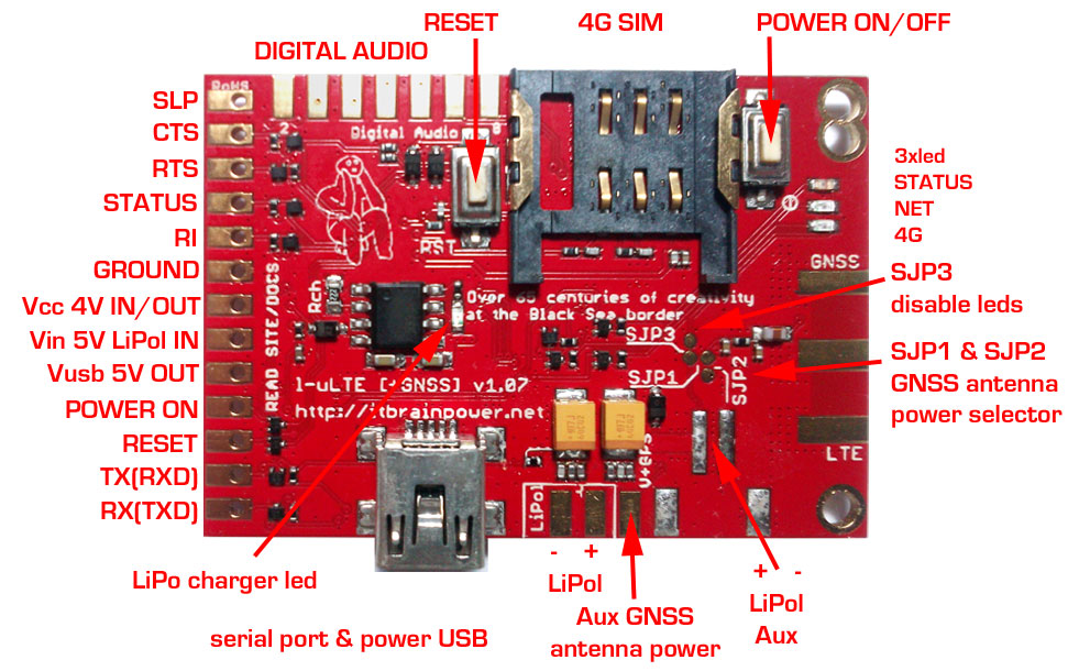
l-LTE LTE/4G + GNSS shield - top details
In the image up here, notice:
a. the "SJP1 and SJP2 - GNSS antenna power selector" solder jumpers. By default, both SJP1 and SJP2 are in "CIRCUIT OPEN" configuration [no connection between solder jumpers pads].
b. the "Aux GNSS antenna power" pad [marked "v+GPS" on the board]- variant for the GNSS antenna power source.
l-LTE shield reference
 l-LTE LTE/4G + GNSS shield - top details
GNSS active antenna use cases
Scenario A: your GNSS active antenna supports powering voltages provided by the Vbat circuit [provided by LiPO battery/charger, 3.10->4.25V]; Eg.: your antenna supports 3-5V powering [most of the antennas supports this]. The GNSS antenna will be powered all time. Scenario B: your GNSS active antenna does not support voltages between 3.10->4.25V [Eg.: your GNSS antenna supports 5V only powering], or you want to implement a sort of power management for the GNSS antenna powering circuitry.GNSS active antenna powering implementation
Scenario A: just make a solder over SJP1 [this will connect Vbat to GNSS antenna circuitry]. Leave SJP2 not soldered [CIRCUIT OPEN]. Done. Scenario B: make a solder over SJP2 [this will connect Vbat to GNSS antenna circuitry]. Leave SJP1 not soldered [CIRCUIT OPEN]. Power the GNSS antenna via "v+GPS" pad and one "GND" pad [the one placed in the right side of the "v+GPS" pad] using proper voltage low noise power source. Done.Additional tips:
1. Always double check what you've done before powering. 2. You may use GPS only antenna, but the GLONASS satellites will be seen with not so good/proper signal/noise ratio [the GLONASS bandwidth is different from GPS one]. In 99% of the cases, this crack will work for you. Anyway, we recommend combo GPS+GLONASS antenna usage. More about itbrainpower.net l-LTE shields : North America versions - European and rest of the world version TUTORIAL PROVIDED WITHOUT ANY WARRANTY! USE IT AT YOUR OWN RISK! - Originally written by Dragos Iosub & itbrainpower.net teamThanks for helping to keep our community civil!
Notify staff privately
You flagged this as spam. Undo flag.Flag Post
It's Spam
This post is an advertisement, or vandalism. It is not useful or relevant to the current topic.
Report Reason
This post is an advertisement, or vandalism. It is not useful or relevant to the current topic.
You flagged this as spam. Undo flag.Flag Post
✅ Your Post Has Been Submitted Successfully!
Your post is currently under review by our moderation team. The review process usually takes up to 48 business hours.
You can track your post's status in the "My Content" section of your profile. Once approved, it will be published and visible to others.

Thank you for contributing to our community!