

How to Crimp Connectors

This is a little how-to guide on crimping connectors for various electronics projects. The art of crimping is sometimes a difficult one, but necessary for 1) reliable and 2) decent looking connections. Breadboards are nice for quick wiring projects but in the long run they are unreliable and look pretty nasty.
To crimp you will need:
- Crimper (or needle nose pliers if you're really good)
- Wire (24 -26 gague usually)
- Crimp pins
- Housings (possibly)
Good crimpers don't come cheap. Expect to pay $30 - $60  dollars for a good one. If you shop around you can find 'ok' crimpers for less. Most crimp tools you find in a automotive section of a store aren't suitable for small wired electrical projects. You need to find something that will fit 22 - 26 gague wires. This crimp tool from Jameco works well for connetors for D-sub serial cable pins (it can also work on female/male crimp pins).

Take the wire you want to crimp something to and strip off about 4 mm from the end. You basically want to strip off enough insulation so that the exposed wire rests in the wire channel (the smaller second one) and the insulation rests in the insulation channel (the larger first one).
 The wire should fit into the channels like the illustration shows. Make sure you have stripped enough insulation, but not too much.
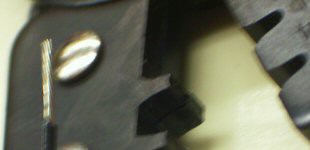
Next, grab your crimp tool. On many tools there will be two different "levels" on the tooth of the tool. This makes sure that the insulation channel has a big crimp than the wire channel, since the stripped wire has a smaller diameter than the insulation. For tools that don't have two different sizes on the tooth, you will have to make two crimps one for the insulation and using a smaller size, crimp the wire.

You can see the two different groove sizes in the picture to the left.
The next two images show how the pin is placed into the crimp too. The larger side of the crimp 'tooth' should be where the insulation channel fits.
Sorry for the blurry picture, but you can make it out, the pin is sitting in the groove with the 'tabs' facing into the groove. It is placed so that when the crimp too is squeezed the tabs bend inwards and create a "heart" shape.


If you apply light pressure to the tool at this point the crimp pin will slide up into the groove and be held in place.
 At this point you can put the stripped end of the wire through the hole that is made by the crimp too and the insulation channel, like pictured:
Do your best to make sure the insulation channel only covers the insulation and the wire channel covers only the wire.
Apply firm pressure to the tool and it should perfectly bend the crimp tabs inwards so that they "bite" into the wire and insulation and form a solid contact.
It should look a bit like this:

You can seein the picture how the wire channel tabs bend inwards and bite into the insulation.

The pins pictured above are pins that would fit into a D-sub serial connector housing with which you can make a serial cable.

To connect something up to a bread board you can crimp on male crimp pins, like the ones I used on a programming cable I made for a Basic Stamp + breadboard.

If you wish to have crimp connections that connect up to square male pin headers you can buy handy female crimp pins.
The final step to making good connections to buy buy some housings to put your crimpped pins into. The housings keep all the pins seperate and easily pluggable.

I hope this helps someone avoid nasty wiring messes in the future. Happy robot hacking!
Thanks for helping to keep our community civil!
This post is an advertisement, or vandalism. It is not useful or relevant to the current topic.
You flagged this as spam. Undo flag.Flag Post
Your post is currently under review by our moderation team. The review process usually takes up to 48 business hours.
You can track your post's status in the "My Content" section of your profile. Once approved, it will be published and visible to others.

Thank you for contributing to our community!