

Building A Maze Solving Robot - Part 3 ... Well, it used to be one ...


As the dead line came closer and closer to when my 'bot needed to be finished I became more and more frustrated,
frantic, and sleep deprived. I worked for hours
in 1st 3 weeks of February! Many all-day-ers and late nights. One night
I even said "I'm staying up till it works!" ... I finally went to bed a
2:00AM. I got lots of great coding done but it just WOULDN'T solve a
path reliably. I tried and tried - adding new sensors, trying new code
- but to no avail. Finally, exactly 8 days before the project deadline
I came to the realization that "this just aint going to work!" Ok, time
to change gears. BUT, before I finish my story I need to tell you what
I DID get done.
As the dead line came closer and closer to when my 'bot needed to be finished I became more and more frustrated, frantic, and sleep deprived. I worked for hours in 1st 3 weeks of February! Many all-day-ers and late nights. One night I even said "I'm staying up till it works!" ... I finally went to bed a 2:00AM. I got lots of great coding done but it just WOULDN'T solve a path reliably. I tried and tried - adding new sensors, trying new code - but to no avail. Finally, exactly 8 days before the project deadline I came to the realization that "this just aint going to work!" Ok, time to change gears. BUT, before I finish my story I need to tell you what I DID get done.
Wheel Encoder Signal Board:
After messing with my wheel encoders for a bit I figured that I really needed to have a circuit that would process the signals and provided good clean 5v-0v signals. The circuit basically takes the different resistances that come from the phototransistor, does and voltage division using a resistor in-between those values, and puts that signal through a comparitor to get a on/off signal instead of a sine wave. The board also provides power for the LEDs. The comparitor is just a LM339 from Radio Shack.
More Servo Modifications:
Yes, once again I started hacking up my servos. Once I completed my signal board I realized that 6 CPR (count-per-revolution) wheel-encoders just wouldn't work. More frustration. After a few multi-hour hacking sessions I got a reliable 180 CPR. I did this by drilling 4 holes into the 1st gear on the gear train, and positioning a LED (just plain red one) and the phototransistor across the hole. The tricky part was getting them in there without touching and grinding up against the other gears. I also had to recalculate and fix all the resistor values in my signal board. I was rewarded for this work by getting a great 180 CPR wheel count.
Left & Right Wall Sensors
To sense the left and right wall in my maze I built and wire-wrapped two IRPD emitter/detector packages. Because the intial distance was too great, I put in a potentiometer to adjust the distance the sensors detect.
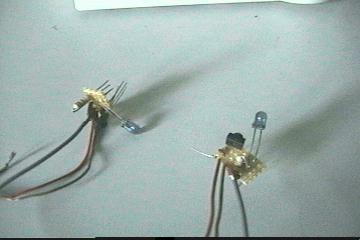
Using the OOPic's oPWM object, I generated a 38kHz signal to run the IR LEDs. My detectors then give a logic high for no object, and logic low for an object. I mounted these on the back sides of the robot.
The Code
Using the nifty new feature on the OOPic compiler I can generate the source code with the appropriate links. Click right here to view the source code.
What Happened:
At my moment of desperation I decided I'd try another, much easier, project - testing the accuracy of dead-reackoning vs. wheel- encoders. It was definately a God-given inspiration: I had everying ready. All I had to do was record the data. Things pro gressed well, and I was able to get some good data. I figured the amount of error in each method by running the robot down a straight line. I measured the amount of deviation from that line using both wheel-encoder and dead-reckoning. The data points to a much greater accuracy using the wheel-encoders. The only instance where the dead-reckoning appeared to be more accurate was when the wheel inaccuracies compensated for the different wheel surfaces. The wheel-encoders were typically 2x better than the dead-reckoning, while this may seem strange, this is attributed to the problems the OOPic has with precise servo control. The only wheel control I was able to get was off/on, so my control was a bit crude. The judges must have liked it, because I got 1st place and 97 points. Since I was the only person in my category the 1st place was default. The regional contest is in a few weeks.
What's Next?
Next I'm planning on turning the 'bot into a fire-fighter. Since I can't make the annual contest, my only hopes for competing are at our local clubs contest. I'm trying to be as optimistic as I can about actually having it running in time. In anticipation of this I've added another 6x6in platform to the top of the 'bot. At the center of this platform I've put a servo with it's horn facing down. I plan on putting a Sharp GPDU12 analog ranger-finder. This will allow me to rotate the sensor back and forth to detect walls. Stay tuned next month for more additions.
As the dead line came closer and closer to when my 'bot needed to be finished I became more and more frustrated, frantic, and sleep deprived. I worked for hours in 1st 3 weeks of February! Many all-day-ers and late nights. One night I even said "I'm staying up till it works!" ... I finally went to bed a 2:00AM. I got lots of great coding done but it just WOULDN'T solve a path reliably. I tried and tried - adding new sensors, trying new code - but to no avail. Finally, exactly 8 days before the project deadline I came to the realization that "this just aint going to work!" Ok, time to change gears. BUT, before I finish my story I need to tell you what I DID get done.
Wheel Encoder Signal Board:
After messing with my wheel encoders for a bit I figured that I really needed to have a circuit that would process the signals and provided good clean 5v-0v signals. The circuit basically takes the different resistances that come from the phototransistor, does and voltage division using a resistor in-between those values, and puts that signal through a comparitor to get a on/off signal instead of a sine wave. The board also provides power for the LEDs. The comparitor is just a LM339 from Radio Shack.
More Servo Modifications:
Yes, once again I started hacking up my servos. Once I completed my signal board I realized that 6 CPR (count-per-revolution) wheel-encoders just wouldn't work. More frustration. After a few multi-hour hacking sessions I got a reliable 180 CPR. I did this by drilling 4 holes into the 1st gear on the gear train, and positioning a LED (just plain red one) and the phototransistor across the hole. The tricky part was getting them in there without touching and grinding up against the other gears. I also had to recalculate and fix all the resistor values in my signal board. I was rewarded for this work by getting a great 180 CPR wheel count.
Left & Right Wall Sensors
To sense the left and right wall in my maze I built and wire-wrapped two IRPD emitter/detector packages. Because the intial distance was too great, I put in a potentiometer to adjust the distance the sensors detect.
Using the OOPic's oPWM object, I generated a 38kHz signal to run the IR LEDs. My detectors then give a logic high for no object, and logic low for an object. I mounted these on the back sides of the robot.
The Code
Using the nifty new feature on the OOPic compiler I can generate the source code with the appropriate links. Click right here to view the source code.
What Happened:
At my moment of desperation I decided I'd try another, much easier, project - testing the accuracy of dead-reackoning vs. wheel- encoders. It was definately a God-given inspiration: I had everying ready. All I had to do was record the data. Things pro gressed well, and I was able to get some good data. I figured the amount of error in each method by running the robot down a straight line. I measured the amount of deviation from that line using both wheel-encoder and dead-reckoning. The data points to a much greater accuracy using the wheel-encoders. The only instance where the dead-reckoning appeared to be more accurate was when the wheel inaccuracies compensated for the different wheel surfaces. The wheel-encoders were typically 2x better than the dead-reckoning, while this may seem strange, this is attributed to the problems the OOPic has with precise servo control. The only wheel control I was able to get was off/on, so my control was a bit crude. The judges must have liked it, because I got 1st place and 97 points. Since I was the only person in my category the 1st place was default. The regional contest is in a few weeks.
What's Next?
Next I'm planning on turning the 'bot into a fire-fighter. Since I can't make the annual contest, my only hopes for competing are at our local clubs contest. I'm trying to be as optimistic as I can about actually having it running in time. In anticipation of this I've added another 6x6in platform to the top of the 'bot. At the center of this platform I've put a servo with it's horn facing down. I plan on putting a Sharp GPDU12 analog ranger-finder. This will allow me to rotate the sensor back and forth to detect walls. Stay tuned next month for more additions.
Thanks for helping to keep our community civil!
Notify staff privately
You flagged this as spam. Undo flag.Flag Post
It's Spam
This post is an advertisement, or vandalism. It is not useful or relevant to the current topic.
This post is an advertisement, or vandalism. It is not useful or relevant to the current topic.
You flagged this as spam. Undo flag.Flag Post
✅ Your Post Has Been Submitted Successfully!
Your post is currently under review by our moderation team. The review process usually takes up to 48 business hours.
You can track your post's status in the "My Content" section of your profile. Once approved, it will be published and visible to others.

Thank you for contributing to our community!