

Assembling A FLED Solar Engine

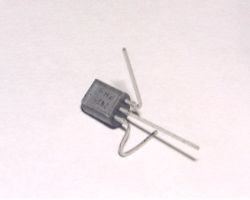
1. Take the 3904 transistor and using a pair of long nose pliers carefully bend the collector leg (that's the one on the far right) so that it is perpendicular to the transistor body as shown in the photograph. Then again using long nose pliers carefully bend the emitter leg (the one on the far left) first perpendicular to the base leg (the middle one) but in the same plane and then back up towards the base leg as shown in the photograph. If you're not sure about this take a look at step 3 and 4 it might be clearer when you can see the assembled engine.
2. Take the 3906 transistor and bend the emitter leg (the one on the far right in the photograph) first perpendicular to the base leg but in the same plane and then over the top of the transistor body. Then take the base leg and bend it perpendicular to the transistor body as shown in the photo.
3. Hold one of the transistors with a pair of long nose pliers so that the base leg of the 3904 is next to the collector leg of the 3906. The legs should overlap by about 6mm - 8mm. With your other hand pick up your soldering iron (which should be hot !), clean the tip and then melt a little pool of solder on the tip. Apply the tip of your iron to the two legs of the transistors to be joined for a second (no more !). The legs will be heated and the solder should flow between them easily. Do not overheat (it may damage the transistors). Continue to hold the transistors together for about two seconds until the solder has solidified.
Now wipe the sweat from your brow!
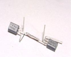
4. Solder the 2.2k resistor between the collector leg of the 3904 and the base leg of the 3906 as shown in the photo. This is best done by first 'tacking' both ends of the resistor to the transistor legs with a small pool of solder on the iron and then applying additional solder to make a more secure joint, once the initial 'tack' has solidified. Using a pair of side cutters trim the excess lead from the resistor.
Almost there !
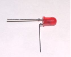
5. Carefully bend the negative leg (the shortest one and also the one nearest the 'flat' on the FLED body) of the FLED at right angles to the positive leg, as shown in the photo.
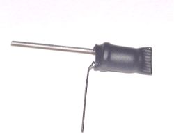
6. Slide a piece of heat shrink tubing over the FLED and using a lighted match shrink the tubing over the FLED body. Whilst the tubing is still hot pinch the end opposite the leads to seal the tube, then cut off any excess tubing.
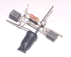
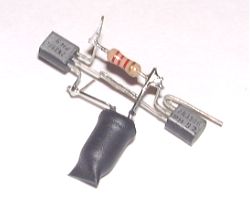
7. Solder the negative lead of the FLED to the emitter of the 3904 (the one that is bent backwards) and the positive lead to the base of the 3906 (to which the resistor is also connected)
8. Trim off the excess leads : FLED negative, FLED positive and 3906 base - as shown in the photo.
Well done you've finished !Editors Note: TotalRobots is a British based robotics company. You can visit their website and order some of their products off their website. The above tutorial is Copyright © Total Robots.

Thanks for helping to keep our community civil!
This post is an advertisement, or vandalism. It is not useful or relevant to the current topic.
You flagged this as spam. Undo flag.Flag Post
Your post is currently under review by our moderation team. The review process usually takes up to 48 business hours.
You can track your post's status in the "My Content" section of your profile. Once approved, it will be published and visible to others.

Thank you for contributing to our community!