

A Simple Cheap and Small Robot Base


Here's instructions on how to make a simple and cheap small robot base.
Ever since my initial start in robotics I've been fascinated with small robots.
Small 'bot seem to have this amazing charm about them. Maybe it's the 'wow!' factor,
or maybe it's 'just because.' This tutorial will step you through the process of
building a relatively small, cheap, and simple robot.
Parts:
2 x Omron/Mac Disk ejector motors
1 x Radio Shack 4AA square battery holder - #270-383
1 x Radio Shack 9v battery clip - #270-324 or 325
1 x Radio Shack proto board - #276-150
1 x Basic Stamp
4 x 24 tooth LEGO gears
2 x 24 chain links
1 x 24 pin IC socket
1 x H-Bride chip or board
At lest 4x headder pins
Hookup wire
1 x 9pin female serial connector - #276-1538
Tools:
Wire cutters
Soldering iron
Solder
Hot glue gun
Tape
A working brain
Part 1 - Mechanics
The first step in the process is to trim down the motors so they will not drag on the ground.
These motors are the ones that make the Mac computers eject their diskettes. If you're having
trouble finding these, look around at your local thrift stores, yard sales, university surplus,
or your friends' attics for older Mac comuters. It is possible to remove the motors without
damaging the computer, or the ejection mechanism. You'll just have to rig up some manual
ejection instead.
Hack down the plastic edges of the motor, so there is no excess around gear. This can easily be
down a Dremil tool, or similar tool. Make sure that you remove the gears when doing this, as the
dust can foul up the gear train.
Next take off the metal plate off the main drive gear on the motor, and glue a standoff onto the
middle of the shaft. I used a small nut for mine. Then glue the LEGO gear onto the standoff.
Make SURE that it is centered and level on the standoff, or your tank drive will be prone to
jumping the gear. Next put together 2 2x1 LEGO bricks with the hole through them. Attach another
24 tooth gear to this assembly.
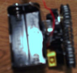
Glue this to the top of the motor, so it forms a 'L' with the
gears at the tips of the 'L'. This setup gives maximum ground clearance for the motor.
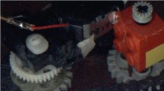
Now
put on the gear chain. Run the motors and make sure that the chain wont break or or jump. (the image directly above doesn't have this)
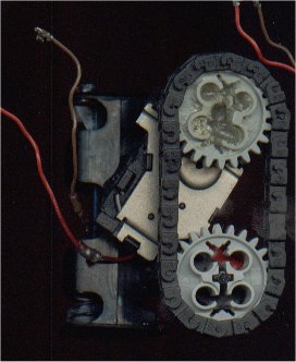
If your chain is prone to bending or jumping you can do a setup similar
to the one below. Allow the idle gear to slide up and down the shaft.
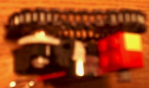
Do the above process for both motor/drive assemblies. Now glue the top
of the actual motor to the side of the battery holder. This forms the
body of your 'bot. Put in 4 AA batteries, connect up the motors, and
watch your creation go!
Part 2 - Electronics
For my creation I build a custom Basic Stamp 2 board. Another small footprint board would work equally well.
Since the BS2 is easy to get and use I use that for the rest of this tutorial.
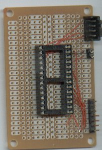
Take the Radio Shack proto board and place the IC socket in the center of it.
Don't solder it down yet, as we have to put some power wires in. For hookup wire,
I just used the small wirewrapping wire from Radio Shack.
If you plan on programming your Stamp directly for the custom board, you will need to
run wires from pins 1,2, and 3 to pins 2,3, and 5 (respectively) on a female 9pin serial
connector. It makes it much easier if you run the stamp pins to a header and make a
programming cable that plugs into the header.
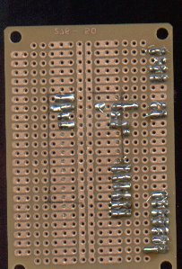
Connect pins 2 and 23 to ground. Then connect pin 21 to the 5v +. This is unregulated power,
so don't put too much into it! Now you can solder down the IC socket and insert the Basic Stamp.
Double check all wiring and the chip direction (pin 1 of the Stamp is the first pin on the right,
with the large chip on the board facing down).
If you are using the H-Bridge driver from Mondo-Tronics then you can connect up a 7 pin headder
to four of the Stamp's pins, then connect it up to the motor driver. Connect up both the motors to
this driver. You now can control your motors via the Stamp! If you'd rather use a all-in-one driver
chip then you can place this into an IC socket on the board. It up to you to figure out the wiring though!
What Next
Hopefully in the next few months we can grow and expand this little 'bot.
My original plan for it was to have at least 2 light sensor, and microphone for sound,
and a few bump sensors. Implementing a subsumption architecture approach we can make it
wander around, avoid obstacles, seek light, and when it is 'scared' by a loud sound it will
hide in the dark. While this sounds impressive, its affect may be lessended by the actual
speed of the 'bot. It would be possible to use a 9v battery in place of the four AA, but there
is the possiblity of frying the motors. 9v batteries also don't have much mAh (miliamp hours)
so the life of the 'bot wouldn't be that long. If you have ideas of what to do next, or you
have build one of these little fellows, drop me a line at [email protected]/gorobotics.
Suggestions on what to name it can also be sent to the above address.
Thanks for helping to keep our community civil!
This post is an advertisement, or vandalism. It is not useful or relevant to the current topic.
You flagged this as spam. Undo flag.Flag Post
Your post is currently under review by our moderation team. The review process usually takes up to 48 business hours.
You can track your post's status in the "My Content" section of your profile. Once approved, it will be published and visible to others.

Thank you for contributing to our community!