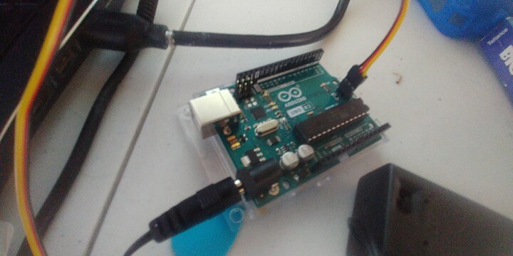
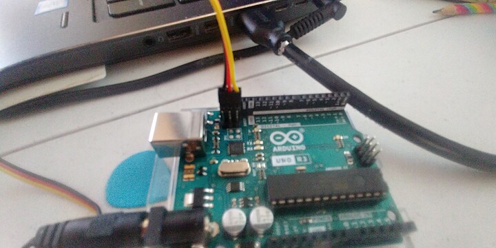
sir!,i want to connect 5 micro servomotors to ardunio with the helpof 9v battery…plz help me
Most RC servo motors are powered at 4.8V to 6V, so if you want to use a 9V battery, you’d need a 5V regulator. Also, 9V batteries are meant to power low current electronics, not servos, so there’s a strong chance that even powering two servos might create brown outs. Last, 9V batteries have very low capacity, meaning the servos won’t operate for long. Micro servos tend to consume high current under load. You should consider using an IO shield for easy connection.
Hi sir,
I connected my arduino with the servo and a potentiometer with cables and it works very good.
In the project I made, i want to control the servo motor, placed in a boat over an antenna. How can i control my servo over a distance, using an antenna.
Sorry for my English (i’m Belgian/Dutch). But i like to control my servo motor, placed in a boat over an distance. In the remote contole is an arduino nano and in the boat an arduino uno… What are the commando’s for programming my arduino?
sorry for my English…
@wdefossez You’ll need a way to send signals wirelessly from where you are to the Arduino. An Arduino Nano on its own does not hare wireless capability (unless you purchased a special unit(, and an antenna only does not transmit or receive. If you don’t want to use a normal RC wireless system, you’ll need the following:
RF device: https://www.robotshop.com/en/general-rf-data-telemetry.html
MCU: https://www.robotshop.com/en/microcontrollers.html (one to read the potentiometer on land, the other to control the servo)
Note that a handheld RC system handles all of this (so no programming needed):
https://www.robotshop.com/en/wireless-rc-pwm-servo-controllers.html
Would you please update the original tutorial because when I clicked on the link to buy the parts, the links point to the whole store? For example, when clicking on the Arduino, it took me to the page where there are a whole bunch of boards. Not sure which one is the correct one?
@long-11 You are correct that this series dates back many years and the products included have long since been replaced. The series as a whole could use an updating. The latest official Arduino Uno:
@cbenson
thank you for you response. I am about to click the button to place my order, but wanted to check with you to make sure that parts I am about to order are all compatible and are what I need. So, here are my requirements:
- No soldering. I just want to connect the servo to the Arduino board without any soldering and need to have the connection to stay permanently.
- Need to have the shafted extend to at least 1 inc
Here are parts I am about to order:
- https://www.robotshop.com/en/arduino-uno-r3-usb-microcontroller.html
- https://www.robotshop.com/en/hitec-hs-422-servo-motor.html
- https://www.robotshop.com/en/sfe-power-supply-9vdc-650ma.html
- https://www.robotshop.com/en/actobotics-2x1-4-precision-d-shaft.html
- https://www.robotshop.com/en/actobotics-set-screw-hitec-servo-shaft-coupler-14.html
As soon as you confirm, i will place my order and start tinkering. Thank you so much in advance for your help
Provided your servo doesn’t encounter much resistance, it should not consume much current and can therefore be powered from the Arduino’s pins. Note that the servo has one 3x1 pin female connector, and you’ll need to break that out to be able to wire black to GND, yellow to one of the digital pins and red to 5V on the Arduino.
@cbenson,
would you please recommend some LED lights that can be connected to Arduino Uno R3 board that does not require soldering?
@long-11 You’ll really like an IO shield like this: https://www.robotshop.com/en/gravity-i-o-expansion-shield-arduino-v7.html
It allows you to use products with 3-pin headers (like servos, sensors, breakout boards. For example, LED lights:
https://www.robotshop.com/en/gravity-digital-piranha-led-module-red.html
https://www.robotshop.com/en/octopus-5mm-led-brick-red.html
hi @cbenson,
this is long-11 (i had to create a new user name). So, I purchased the parts I listed in March. Specifically, I bought the R3 Uno board along with the Hitek HS-422. I wrote the source code the way you showed, but not sure how to connect the servo to the Uno. I tried both the 3 pins in the middle of the board and the one next to the USB port, but the servo won’t rotate. Would you please show which pin I should connect the servo to?
@longlac Welcome back. You didn’t opt for the shield in the previous reply? The objective of using that was to easily connect the servo, LEDs etc. Ideally the Arduino’s pins would not power the servo motor directly, but if there’s minimal load (i.e. it won’t consume much current at all), you’d connect the black cable to GND, the middle red cable to 5V and the yellow to a digital pin. It’s best not to connect the pins and provide power (can fry some or all electronics). Feel free to provide a clear photo showing the connections before providing power / connecting to the computer via USB.
I was hoping that I did not have to buy the shield as I tried to keep the cost down for my customers. I am thinking that since I am connecting to the pins different than what you showed in the tutorial, I need to change the source code, but not sure what pin number to use for my connections
Oh dear no - those pins are not used for that purpose at all. Just because they fit one into the other does not mean that’s their function. Robotics requires elements of understanding mechanics, electronics and programming, and if you just plug things into each other, bad stuff tends to happen (including fires). According to the tutorial which corresponds to this thread:
- Connect the black wire from the servo to the GND pin on the Arduino
- Connect the red wire from the servo to the +5V pin on the Arduino
- Connect the yellow or white wire from the servo to a digital pin on the Arduino
Look at how the servo is connected in this image (notice that there are three additional single wires needed):

@cbenson, would you please provide the link to the extra wire so i can purchase it and use it to connect my servo to the Uno? Also, as I stated back in 2017, I like to avoid soldering. Would the extra wire require soldering?
You’d need standard male to male wires. They’re the most common, so you have an abundance of choice. No soldering required. If you want to keep the same color scheme and don’t need tons of them:
If not in stock:
Since the color actually doesn’t play any other role than helping you see what’s wired where, you can use black to black, red to red and yellow to white.
@cbenson,
i ordered the jumper wires you mentioned and got the servo to rotate. Thank you so much for your help. I am now getting more ambitious and want to do more: I’d like to use my servo as a clock. I want to, say, move the servo once at 1 o’clock, twice at 2 o’clock, three times at 3 o’clock and so on and so forth. I think i can write the code to do this. What I need help with is how to allow users to set the time. I guess I need a switch/button to allow the user to set the hour and the minute. Based on that input, I can write the source code to compute the top of the hour and move my servo. Not sure if this is out of scope for this forum, but if you can help with that, really appreciate it
If you want it to be a stand-alone project (i.e. not connected to a computer) consider four seven-segment displays or a small character LCD, for example:
This uses I2C communication, so you’ll need to use wires to connect it to the right pins, and learn about communicating with I2C devices.
If you want accurate time, you’d need a real time clock module (“RTC”), for example:
If you’re using Arduino, you can consider a shield:
Note that the pins are not broken out, so connecting the servo again will be a bit more difficult.
Using a ROMEO or BotBoarduino which breaks out the pins on the sides will allow for both:


