


Robot Leg Torque Tutorial
The Robot Leg Torque Tutorial is intended to complement the RobotShop Leg Torque Calculator found in the Robot Design Tools section of the RobotShop Learning Center. This tutorial explains how to find the torques acting at each degree of freedom of a 6-legged (hexapod), 3DOF / leg “insect” robotic leg.
Hexapod (6-legged) robots are most commonly configured in either two rows of 3 legs (3+3) or at 60 degrees from each other and an equal distance from the center. This tutorial will explain only the 3 + 3 configurations. With some modification, the equations can be adapted to find the torque required at each joint of an n-legged walking robot with an "insect-like" leg configuration.
Dynamic stability:
A dynamically stable walking robot must be in motion in order to prevent it from falling over. If the robot were to stop while walking (walking pattern can also be referred to as a “gait”), the center of mass would cause it to fall over.
Static stability:
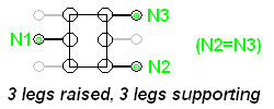
A statically stable robot can be stopped at any point during its gait and it will not fall over. In the case of a hexapod, so long as 3 legs are always in contact with the ground and the center of mass is located within the triangle formed by these feet, it will be statically stable. This tutorial considers only this situation, as shown in the image below (N is the “normal force” the ground exerts on each foot):
The links that make up an “insect” leg do not necessarily need to be perpendicular to one another, as shown in the image below:
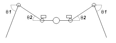
The angles are taken between the horizontal and the link and it is assumed the legs are configured the same on both sides. The following assumptions must also be made in order to simplify the calculations and inputs required: 1) 6 legs, configured as two rows of 3. 2) All the legs are identical If you are unfamiliar with the concept of torque, you are encouraged to first read through the Robot Arm Torque Tutorial. In order to find the torque acting at each joint, a free-body diagram must be drawn. All supporting legs must be considered:
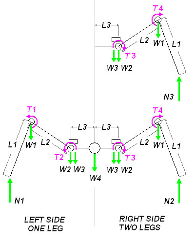
N1,2: normal (reaction) force L1,2,3: length of the link W1,2,3: weight of each actuator (W2,3 are assumed to be very close) W4: Weight acting at the center of mass T1,2,3,4: Torque acting at each joint (each side is different) In order to determine the torque T1 acting at the "knee", we must assume that the rest of the structure is rigid (not moving). Similarly, when finding T2, acting at the "hip" the rest of the structure (including the torque T1) is considered rigid. If you are uncertain as to the direction of the torque, consider applying torque in the opposite sense and notice that the leg would retract. The links are considered to be massless. The torques T3 and T4 will be different than T1 and T2 because the central weight is not being supported equally among the three legs. In this case, T1>T4 and T2>T3, so we will only calculate T1 and T2 (an actuator is chosen based on the maximum torque required). The weight W4 acting at the center of the robot when 3 legs are raised is a combination of various parts below:

The weight of the robot is assumed to be evenly distributed on both legs on the right side, so the reaction forces, N2 and N3 are equal. Three legs must support the entire weight of the robot, as well as their own weight:
The value of the normal force N2 can be found by doing a torque balance about N1:
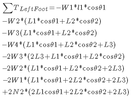
Although long, the equation uses only known variables, and since the combined torque about the left foot is zero, this equation will allow you to solve for N2. This value is inserted into the equation above, to solve for N1. Using conventional notation (counterclockwise is considered positive) we can find the torque about the knee joint:
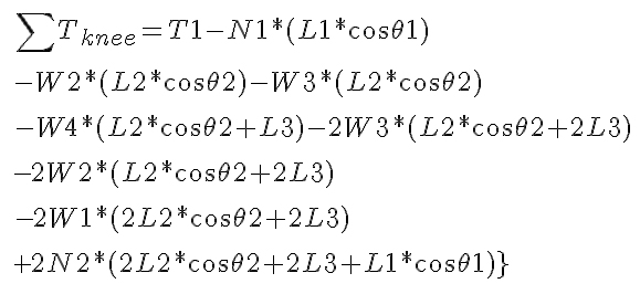
The above equation considers that there are three legs supporting the robot on the right side. As with the previous equation, the sum of the torque for an object not in motion is zero (in this case the leg is simply supporting the body and not moving). The torque needed at the hip joint can be found as well by doing a torque balance about that point:
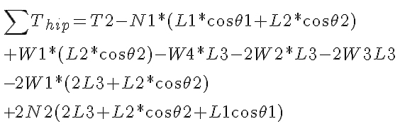
Once more, the total torque about the point is zero because it is not moving, allowing you to solve for T2. At this point, there are two different approaches you can take: one decision is to make all 18 motors identical, while the other is to select motors based on the torque required at each joint. There are arguments to both and the decision is yours. The final torque to calculate, exerted at the shoulder, is used to propel the robot forward. Keep in mind that a hexapod with three degrees of freedom per leg has a total of 18 degrees of freedom and as such there are configurations possible where less torque will be required when climbing an incline. One example of this is when the rear legs are used to push the robot up the incline, while the front legs pull it up. In order to find the torque required to move the robot up an incline with each leg positioned identically to the rest, a different perspective must be chosen. If your robot will not encounter steep inclines or will move in roughly horizontal planes, then it is a good decision to choose the same motor used in either the knee or the shoulder. The torque calculation required is similar to that of the Drive Motor Selector Tutorial, where the maximum torque will arise when the robot is on an inclined surface. The difference in perspective is such that the “wheel” is placed horizontally rather than vertically. The force of friction acting on the three feet (the other three are raised) is what allows the robot to move up the incline. In the first scenario described here, the robot must simply maintain its position on the incline.
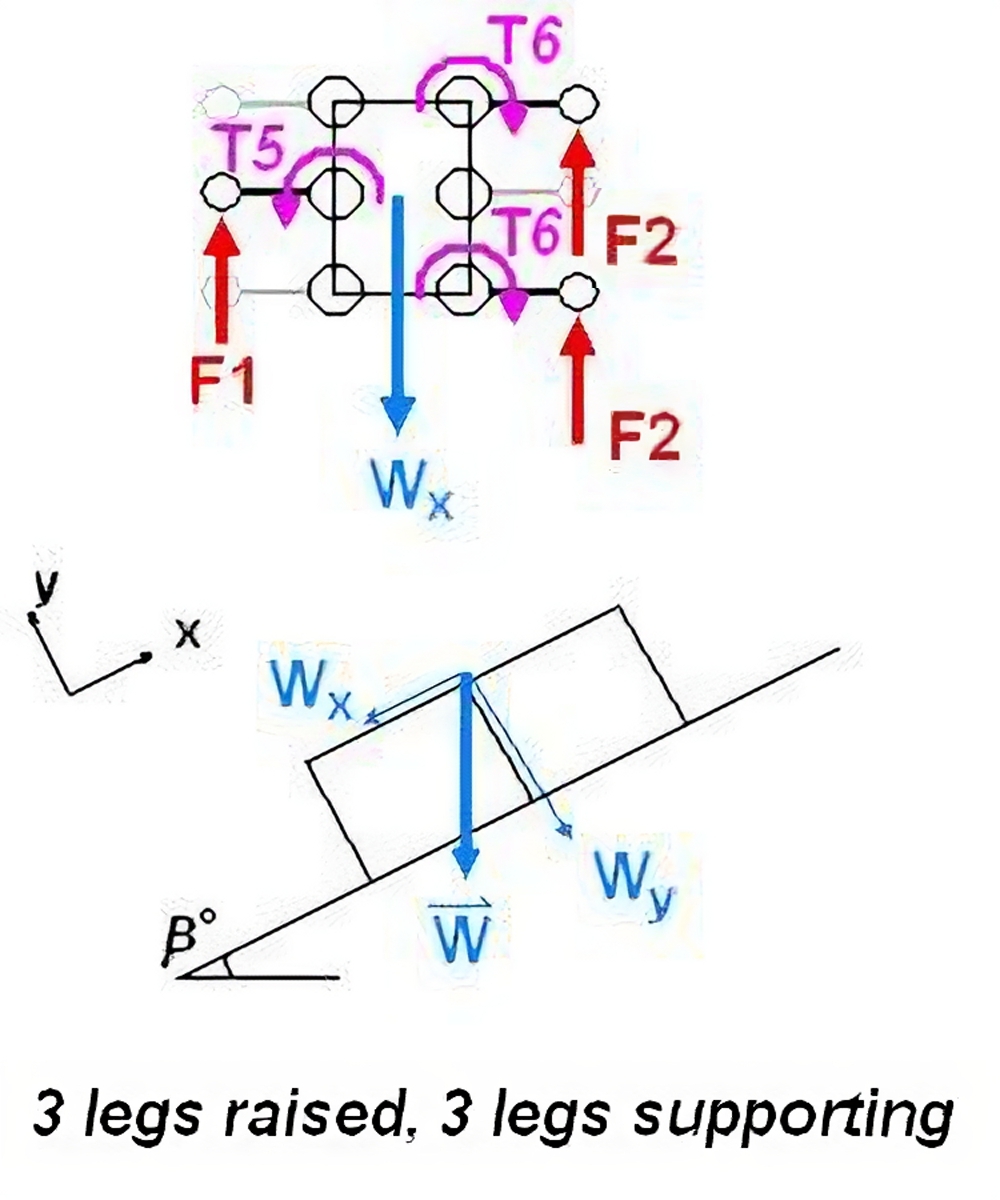
The reaction forces counteract the weight of the robot which would otherwise cause it to slide down the incline. The magnitude of the weight of gravity along the slope can be calculated as: ![]() A torque balance about the left shoulder actuator gives:
A torque balance about the left shoulder actuator gives:
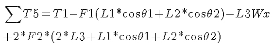
In order to move straight, the force on the left side must equal the force on the right side, otherwise, the robot would begin to turn. ![]() The torque T2 will be less than T1, so a second equation is not necessary. The torques above represent the required to keep the robot stationary and do not include the extra torque required for motion. When looking for an actuator, you are encouraged to add 25% to each torque as a safety factor.
The torque T2 will be less than T1, so a second equation is not necessary. The torques above represent the required to keep the robot stationary and do not include the extra torque required for motion. When looking for an actuator, you are encouraged to add 25% to each torque as a safety factor.
For further information please visit the RobotShop Learning Center. Visit the RobotShop Community Forum in order to seek assistance in building robots, showcase your projects or simply hang out with other fellow roboticists.