


Calculating Angles Based on x, y, z
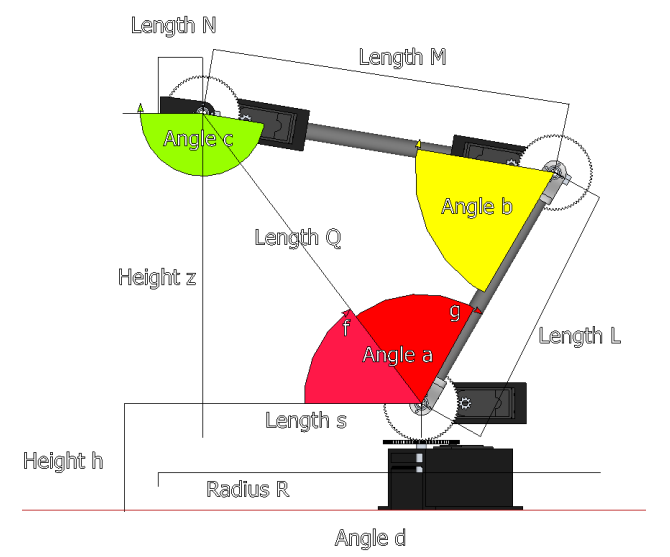
The equations below are done in reference to the image above. The robot shown is the RobotShop M100RAK. This is just one way of calculating the joint angles of a four degree of freedom robotic arm based on coordinate (x,y,z) of the end of the gripper. It is up to the user to then transfer the equations to a programming software.
Note 1: The equations need to be calculated in RADIANS (not degrees) and then converted back to degrees. We also suggest including constraints to ensure the given point can be reached by the arm. Spaces in the equations have been added but are not needed.
Note 2: The letters used for lengths and angles are random and capitalization is not important.
L
The length of the shoulder axis to the elbow axis
M
The length of the elbow axis to the wrist axis
N
The length of the wrist axis to the end of the gripper (or the desired point)
R = [ (x^2) + (y^2) ] ^ (1/2)
Represents the radius from the axis of rotation of the base to x,y
s = R - N
Since the arm has four degrees of freedom, there are infinite solutions possible for the arm to reach point (x,y,z). We will therefore introduce an artificial constraint and keep the gripper at a specific angle to the horizontal, and calculate for a new coordinate (x1, y1, z1) of the wrist axis.
Q = [ (s^2) + (z^2) ] ^ (1/2)
This is the distance between the shoulder axis and the wrist axis
f = atan2 (z, s)
This is the angle between the horizontal and the line Q. The atan function would return two angles whereas the atan2 function determines the correct angle based on the x and y coordinate. The actual height is h + z which can be taken into account when inputting
g = acos [ ( (L^2) + (Q^2) - (M^2) ) / (2*L*Q) ]
This is the angle between line Q and link L using the law of cosines. Use the equations above to find angles a, b, c and d:
a = f + g
This is angle 'a' above.
b = acos [ ( (M^2) + (L^2) - (Q^2) ) / (2*L*M) ]
This is angle 'b' above using the law of cosines.
c = -b - a + 2*pi
This is angle 'c'. Angle c is kept horizontal to the (x,y) plane.
d = math.atan2 (x, y)
This is the angle 'd' of the base.
Therefore angles a, b c and d can be calculated knowing the lengths of each segment and the x, y and z coordinates of the end of the gripper. This same method can be used for three degree od freedom robotic arms or three degree of freedom legs (ex on a hexapod legged robot). Robotic arms with additional degrees of freedom can use an approach with matrices (not explained here).