


Hacking a Cuckoo Clock
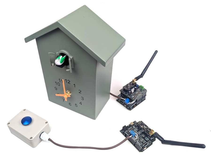
When you just can't get enough of that Cuckoo chirping, you install an on-demand Cuckoo button. That's what we did when we hacked this Cuckoo clock. To do so we made a custom wireless button controlled and a two-node network with matching nRF24L01+PA+LNA. Let's dive into the details.
Introduction
The actual "Hack" is straight forward and requires little explanation. On the back of the clock is a manual push button that activates the little birdie. We simply spliced the button and added wires on either side of the button, essentially adding a second parallel button. Now when the wires close the circuit by touching, a button press is mimicked. We can use a small relay to control this button easily.
To make this a fun project, we wanted to physically remove the button from the clock. So far removed that it seems silly when pressing a random button that a Cuckoo clock goes off way over there.
To make this happen we used the PTSolns NRF-Shield, which allows for very easily adding RF communication to an Uno board, by simply stacking it as a shield on top and setting the code up. It couldn't be easier. On the receiver end, we also inserted a custom shield that contains the relay operation. This custom shield was made with the PTSolns Proto-Shield, a very flexible prototyping board that allows for endless configurations and applications. In the next sections we discuss the BOM, how things are connected, and the code that brings it all together.
BOM
Besides a Cuckoo clock to hack, you will also need the following items:
- 2x PTSolns Uno R3+ microcontroller development board.
- 2x PTSolns NRF-Shields.
- 1x PTSolns Proto-Shield.
- 2x nRF24L01+ RF modules. Any form factor of the standard three will work. In our project we used the +PA+LNA to get further reach.
- 1x relay that can be driven by a microcontroller. We used the LCA110 solid state relay. We also used a matching IC socket, but this is not required if you don't plan on removing the IC from the shield. Though, we typically recommend to never solder ICs directly and use an IC socket instead.
- A couple of 2-Pin screw terminals to connect the wires to (both the Tx and Rx nodes have wires going into a screw terminal). We used 5.08mm/0.2in pitched screw terminals to accommodate for heavier gauge wire.
- A custom bottom as shown in the cover picture. This can be any sort of button, switch or toggle as long as when activated it closes the circuit it is attached to.
- Power sources for both nodes. We just used wall adapters with 7V DC output and plugged right into the barrel jack.
Assembly
This project consists of a transmitter node (TxN) and a receiver node (RxN). They are both similar in terms of the nRF setup, but the RxN also has a custom shield (made with the Proto-Shield) stacked in between.
Lets talk about the TxN first, followed by the RxN. Finally, we will discuss how to hack into the button of the Cuckoo Clock itself.
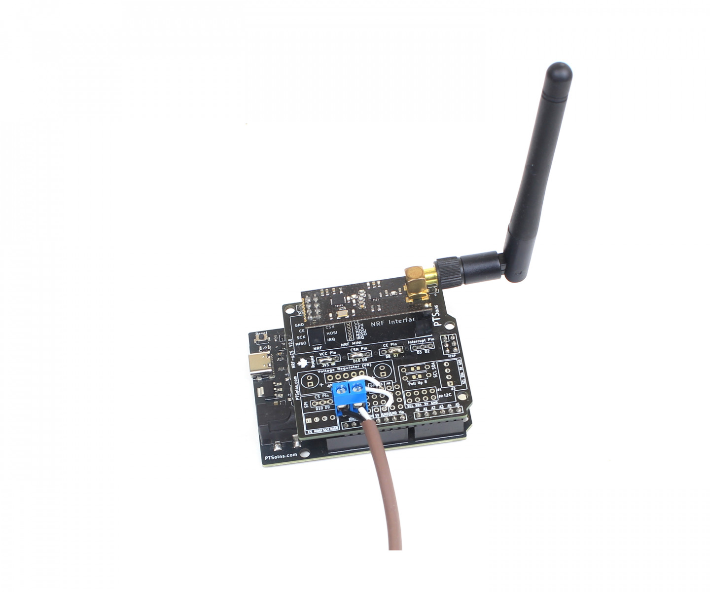
TxN Hardware Setup
The Transmitter Node TxN consists of the NRF-Shield stacked on the Uno R3+ (actually, any similar form factor dev board would work, including the Leonardo and other Uno versions).
The NRF-Shield simply has the headers soldered in place. NOTE: Make sure to include the ICSP header as this is the one used to communicate to the nRF module via SPI. If you omit this 2x3 Pin header, the nRF will not receiver any signals.
The user is encouraged to read the NRF-Shield Datasheet, as it outlines important hardware selection settings. Here we will simply state the hardware selection settings for the TxN (we simply soldered the corresponding jumpers). They are:
- VCC Pin: 3V3
- CSN Pin: D10
- CE Pin: D7
- Interrupt Pin: Not used
Note that the user can change these hardware selection pins, but then must take care to update the corresponding sketch accordingly.
To finish the TxN we added a 2-Pin 5.08mm/0.2in screw terminal on the prototyping section onboard the NRF-Shield. One pin of the screw terminal is connected to the ground pin (GND), while the other is connected to D5 (which is conveniently made available on the prototyping section). With this screw terminal setup, the user can attach any custom button module. The Cuckoo Clock is triggered when D5 is pulled to GND via activation of the button (or switch, or toggle, etc.).
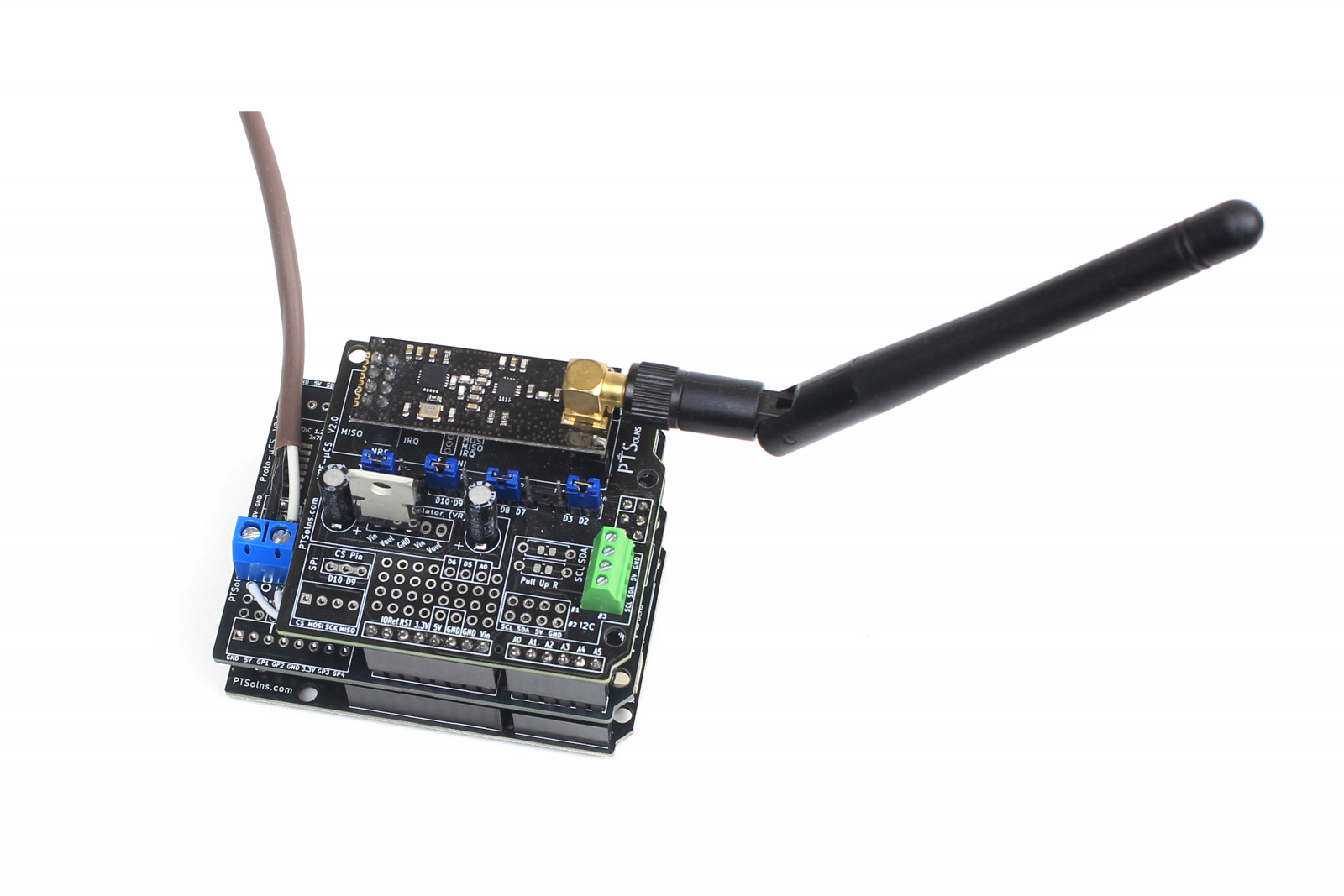
RxN Hardware Setup
The RxN has a similar setup for the NRF-Shield. The only difference in hardware selection pins is CSN is moved to the D8 pin, for no particular reason other than to change things up. Where the difference in the RxN comes in is in the custom prototyping shield that is stacked in the middle.
We are using the LCA110 solid state relay, which is driven by the D4 pin on the Uno below. This relay works great for these low power applications. It is small, fast, and cheap. So we love using it.
The following pin connections are made to the LCA110.
- Pin 1: D4
- Pin 2: GND
- Pin 3: Left floating, not connected
- Pin 4 jumper wire to Pin 6
- Pin 5 jumper wire to screw terminal
- Pin 6 jumper wire to screw terminal
With this arrangement the relay controls the two pin on the screw terminal. When D4 is driven HIGH, Pin 5 and Pin 6 close. Therefore, we run wires from the screw terminal into the Cuckoo Clock, added in parallel into the manual activation button on the back of the clock (more on that below), then simply driving D4 HIGH closes the relay on Pin 5 and 6, and this mimics the activation.
Hacking the Cuckoo Clock
On the back of the Cuckoo clock is a manual push button labeled "Adjust". When this is pressed the little birdie comes out and makes one extra cuckoo sounds than the previous time he made an appearance. This continues until 12 sounds, and repeats back to one.
We opened up the clock and ran a two stranded wire into it from the back, right next to this adjust button. From there we simply cut the wires of the button and wired in, in parallel, our wires that are coming from the screw terminal on the RxN. That's it, it really was that simple. Took about five minutes to set up.
Code
The easiest way to upload the code is to use Arduino IDE. Simply copy and paste the scripts for the TxN and RxN and compile it onto the respective Uno R3+ development boards.
Note that these two sketches leave much to be desired. They are simple but do fail sometimes. For example, there is no ACK sent and sometimes a button press signal is missed. Due to the lack of ACK, the missed signal is not resent. This means the birdie doesn't sing. But you just have to hit it again. There is also no software debounce to handle the mechanics of a button closing (rapid repeated closing). However, these sketches do work with bare minimum code written. The reader can improve upon these as desired.
Find the two sketches for the TxN and RxN attached to this post.
Conclusion
We hacked a Cuckoo clock to make the little birdie sound upon a remote button press. This was a fun and quick project, but it demonstrates what can be done with Uno shields and a bit of creativity. As always, Happy Tinkering!