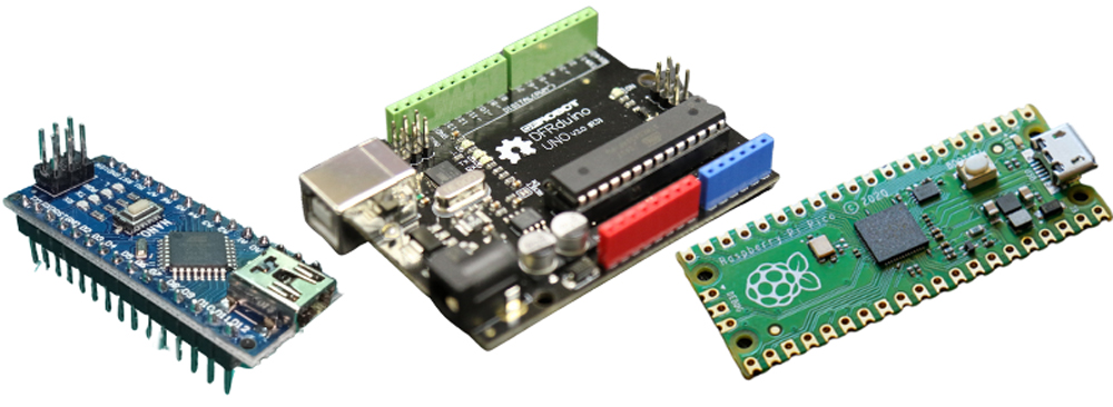
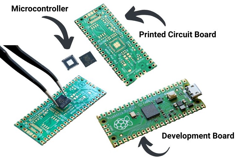
For a beginner, choosing the right microcontroller may seem like a daunting task, especially considering the range of products, specifications, and potential applications. There are many different microcontroller boards available on the market: Arduino; BasicATOM; BasicX; Raspberry Pi Pico; POB Technology; Parallax. Pololu; Miscellaneous (Robotics Connection, New Micros, Rogue Robotics), and many more. Unless you plan to control your custom robot using a tether or controlled via R/C signals, you will need a microcontroller. Note that we use the term "microcontroller" to refer to a complete breakout board with an onboard chip. When considering the right microcontroller, ask yourself the following questions:
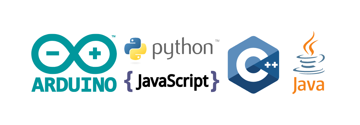
The lowest-cost microcontrollers are currently PICs (Programmable Interface Controllers), though are not necessarily the easiest to program or use. More user-friendly intermediate programs are available for microprocessors and are often written in C, Basic or other user-friendly variations and PCBs are added to make PICs easier to use and interface with. If you do not have an idea which programming language you would like to learn, consider choosing a microcontroller with a large user community and existing free libraries.
Most companies sell both a microprocessor as well as a corresponding starter board. There are many advantages to a starter board: they usually include power regulation, easy computer connection (via USB or Serial), provide protection against faulty wiring, and many useful connections (such as a solder-less breadboard). A chip alone will need extra components in order to be programmed and powered. Some add-on boards offer significant versatility: some come with motor controllers, sensor boards, LCD displays, and more.
At a minimum, most microcontrollers are capable of digital input and output. Some (though not all) have built-in A/D converters which allow direct interface with analog devices. Another useful feature offered on some microcontrollers is a regulated voltage output pin (usually 5V); the Arduino microcontrollers offer both a 5V and 3.3V output pin.
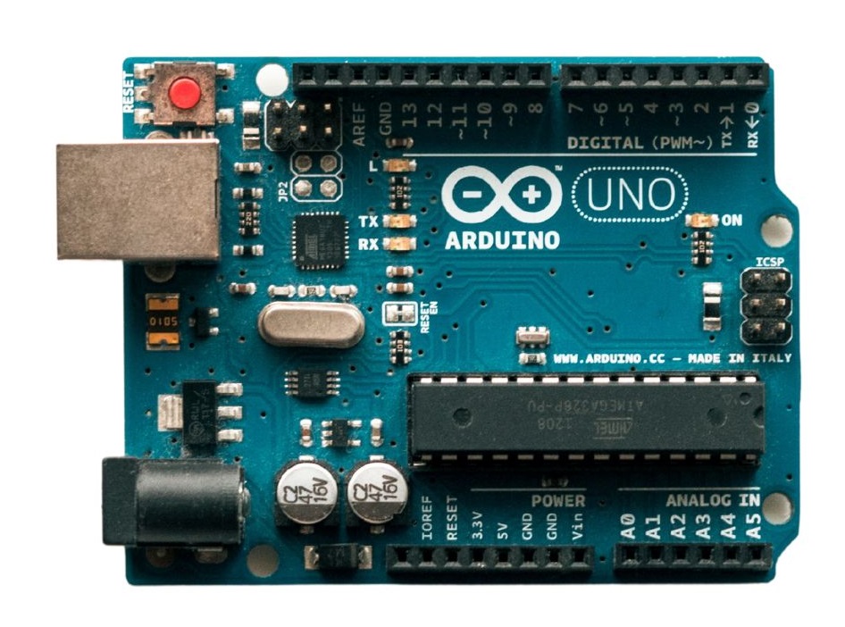
The number of free pins decides how many different devices you can connect to the microcontroller. There are two basic pin types: digital input/output (I/O) and analog input/output (I/O). Other pin types include transmit/receive (Tx/Rx), Power, and ground (GND). A beginner should consider allocating one pin to each function below:
- on average, one digital pin per digital sensor*
- one analog pin per analog sensor
- one digital pin per motor (connected via a motor controller)*
- one digital pin for Tx (transmitting data)
- one digital pin for Rx (receiving data)
*Some sensors and motor controllers may require multiple pins, or allow you to operate several devices using only one pin. Some microcontrollers do not have any analog I/O pins, so you must buy an additional analog-to-digital converter. A digital pin allows your microcontroller to communicate with other digital devices (as well as other microcontrollers) and must follow specific communication protocols as defined in the product’s user manual.
Digital example
The SSC-32 servo motor controller requires a digital signal with the following format: "#4P1250S200" which it interprets to be servo number 4 (the SSC-32 can control up to 32 different servos), pulse 1250 milliseconds, and speed of 200. Any other format would not be accepted and the SSC-32 would do nothing.
Analog example
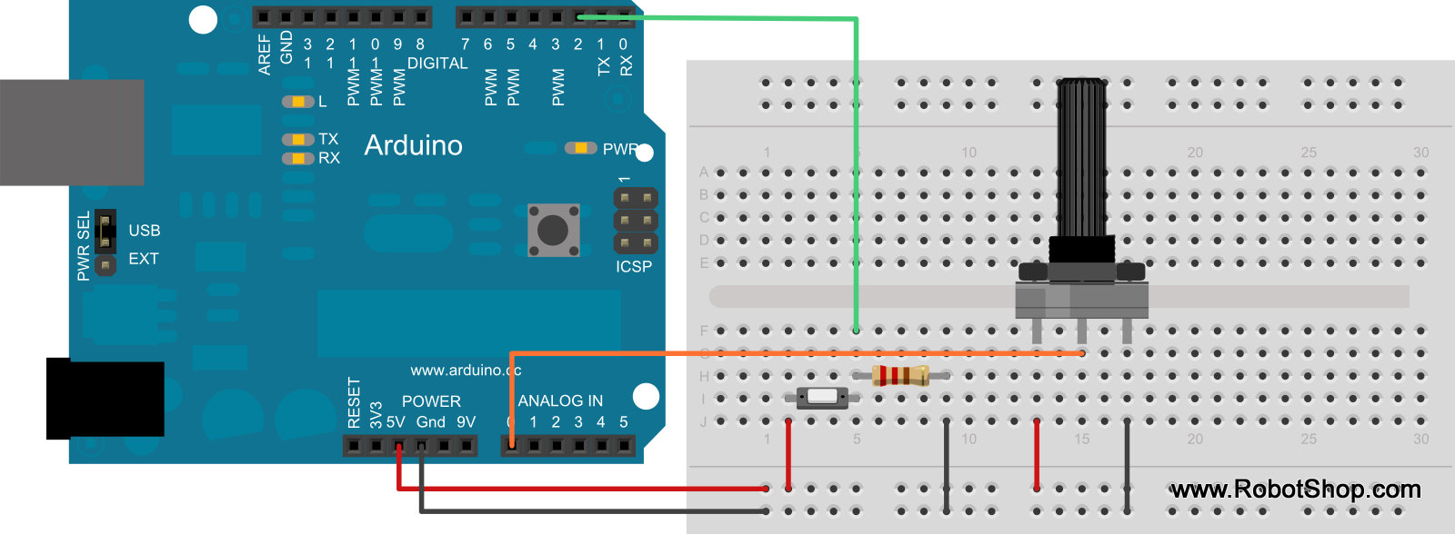
A potentiometer is an analog device – the reading, which is taken from the center pin, is proportional to the angular position of the shaft (and is also proportional to the input voltage). If a user connects the potentiometer to a 5V supply and turns the shaft, the output (which will be between 0 and 5V) will correspond to fully clockwise / fully counterclockwise positions (usually 0 to 300 degrees of rotation). The A/D converter interprets the voltage and converts it to a numeric value (For example, 0 remains 0, 2.5V becomes 512, 5V becomes 1024 or similar depending on the number of bits: 8, 10, or 12).