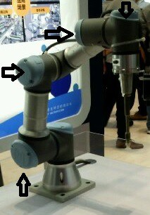
Basic arm robot structure
In industrial robotics, a traditional manipulator arm is a robot structurally composed of a series of links (physical bodies) connected to each other by joints, as shown below:
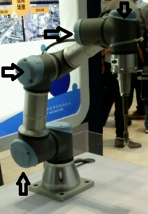
The figure shows a manipulator arm with 4 rotational joints. The joints can be:
1) of rotation
2) of translation
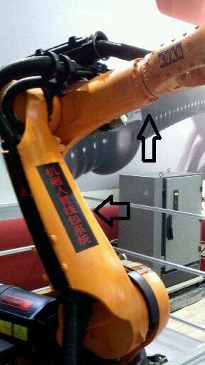
The first type of joint permits rotation of the link, the second type of joint permits the translation of the link. In the following picture is showed another industrial robot where is possible to see two links:
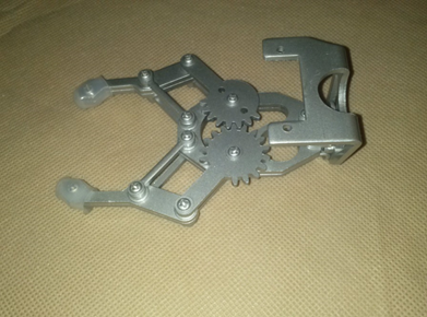
Is very important to understand that the component that can often change in an industrial robotic arm is the terminal organ also called END EFFECTOR. For example, if the robot has to cut an object, then the terminal organ will be a knife or a similar tool, while if the robot has to drill, then the end effector will be a tip, and so on. In the following picture is showed a particular end effector ():
A manipulator arm is, in fact, a type of robot and as such is an agent that is a system that interacts with the surrounding environment and does so through the use of sensors and actuators. A simple example of agent is showed in the following picture:
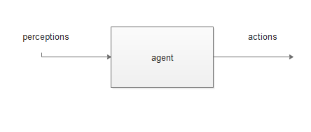
sensors are used to read perceptions from the environment, while actuators are used to act on the environment. There are several types of sensors on the market but as far as actuators are concerned there are three possible cases:
1) pneumatic actuators
2) hydraulic actuators
3) electric actuators
In the robotic arm, DC motors are usually used as electric actuators. The actuator is part of a more complex system called an actuation system which is shown below:
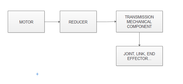
In particular, the motor transforms the primary energy (electric, hydraulic, pneumatic) into mechanical energy useful for motion. Instead, the reducer allows to modify the kinematic / dynamic parameters of the motor. For example, by reducing the motor speed you can have an increase in torque generated. Then, the transmission organ allows the movement to be transmitted from the reducer to the final organ (link, end-effector, ...).
Is very important to know that each type of actuators has got limits and advantages. In particular, motor torque means the mechanical moment applied by a motor to a transmission member (for example a transmission belt). The following picture show a simple example of electrical DC motor:
The driving torque is given by the sum of two terms:
Resistant torque (C_r)
Inertia torque (C_i)
Therefore:
C_m = C_I + C_r
Where is it:
C_i=inertia torque
C_r= resistant torque
C_m= driving torque
Instead for the sensors, there are many different types of sensors in the robotic world. For example there are distance sensors, temperature sensors, pressure sensors, and so on. Often, in entertainment robotics, ultrasonic sensors are used as distance sensors, such as the SRF05 sensor shown in the figure:
In the following picture is showed the same sensor controlled by Arduino board:
In the following picture is possible to see an hand controllder via Arduino. When an object is near to SRF05 sensor, the fingers of the hand began to move closing the hand.
In the following picture is showed another type of sensor called bending sensor:
In few words, this type of sensor change internal electrical resistance when it flexes and therefore when the geometric dimensions change.


