


- Open the Encoder_disk.pdf and print it onto the Avery 8160 address label paper
- Use scissors to cut out the Encoder disk graphic along the dashed lines from the label paper and cut out the center hole using the dashed line as a guide

- Peel off the paper backing from the encoder disk graphic from Step 3
- Attach the encoder disk graphic to the back of the round servo horn and center the encoder disk graphic hole around the servo horn spline boss
- Smooth out the encoder disk graphic to remove any air bubbles or wrinkles


- Place a small drop of hot melt or super glue onto the micro servo motor shaft boss. Use hot melt glue as a temporary fastener but use super glue for the final permanent attachment.
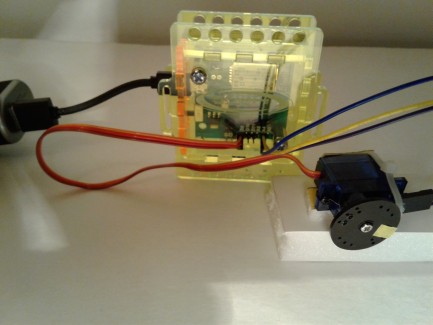
- Attach the Tamiya Analog encoder ensuring that the hole in the Tamiya Analog encoder circuit board is centered around the micro servo motor shaft with the sensors pointing up/away from the motor

- The cables provided with the Tamiya Analog encoder need to be modified to work with standard ground-5V-signal configuration on microcontroller analog input pins
- Swap ground and 5V wires on one end of the Analog sensor cable so that the 5V wire is in the center of the pin connector and the ground and signal wires are on the edge position of the pin connector
- Attach the unmodified end of the cable to the Tamiya Analog encoder pins
- Attach the modified end of the cable to the analog input pins of the Arduino microcontroller ensuring that the ground wire on the Arduino pin is connect to the ground pin of the Tamiya Analog encoder
- Attach the Micro Servo motor PWM cable to the D9 PWM pins of your Arduino microcontroller


- Mount the round servo horn with the encoder disk graphic onto the micro servo motor shaft and attach it using the provided servo horn attachment screw
Arduino Version

- Connect the modified end of the encoder sensor cable to the Analog 4 port of the Arduino observing the correct Ground-5V-Signal pin orientation
- Connect the Micro Servo Motor PWM connector to the D9 pins of the Arduino controller
- Connect Arduino to a power supply
Raspberry Pi Version


- Stack the Pimoroni Automation Phat to the Raspberry Pi GPIO header
- Stack the SparkFun Pi Servo HAT on top of the Pimoroni Automation Phat
- Connect the Signal pin of the Analog Encoder sensor to the ADC 1 connection on the Pimoroni Automation Phat
- Connect the Ground and 5V pins of the Analog Encoder sensor connector to the respective Ground and 5V connections on the Pimoroni Automation Phat
- Ensure that the SparkFun Pi Servo HAT Power supply isolation jumper is in open mode (see vendor manual) before connecting the battery power to the hat
- Connect battery power to the Raspberry Pi and SparkFun Pi Servo HAT
Arduino Version

- Copy, clone or download the Arduino Encoder Encoder.ino, Encoder.h and Encoder.cpp demo code from github
- Open the demo code in the Arduino IDE and select your board from the IDE Tools menu
- Upload the code to your board
- Once the Arduino board resets it will start the program and run through a sequence of predefined motions that illustrate how to control the Micro servo motor using the Tamiya Analog encoder
Raspberry Pi Version

- Copy, clone or download the encoder.py Python Encoder demo code from github onto your Raspberry Pi SD card
- Open the demo code in the Python 3 Idle IDE and run the code from the IDE Run menu
- Once the program starts it will start the program and run through a sequence of predefined motions that illustrate how to control the Micro servo motor using the Tamiya Analog encoder. Uncomment to code labelled interactive mode to enter position commands from the Python shell command line
- You can test an example robot with encoder controlled Micro Servo motors on the free droidguru.net Web site
- Goto: droidguru.net. Watch the tutorial first if you don't know how it works (Help menu). Joystick steers the robot and the A button fires the Airsoft gun unless it's out of BB's or battery dies. (Best when viewed on a laptop/desktop computer)
- Follow these steps to start using the example robot
- Login as a Guest
- Select the Wheels room from the Join Room Panel
- Select the Drone Patrol 1 robot from the Room members panel
- After the countdown timer completes you can control the robot with the joystick or jog buttons
- Reselect the Drone Patrol 1 robot from the Room members panel to start a new robot control session
- The virtual joystick steers the robot and the joystick job arrow buttons control jog/vernier/incremental motor movements using the Analog encoders to better align the airsoft gun with the targets