


Z-BOT
I would like to introduce my robot. Its name is Z-bot. It is a four wheeled robot car, which I made in 2012-2013. This work was my thesis work at BSc level, at University of Szeged, Hungary. I am a computer science engineer. This was my first ever robot to came alive, and also a last too, because I had no time for these kind of hobby.
So first of all, I want to add some background of sensors, actuators and after that I will explaine my Z-bot’s boards, platforms and some kind of behaviors.
In this picture, you can see my robot’s block sketch. I used two microcontroller C8051F410 and C8051F120. These 8 bit controllers based on Intel 8051’s controller, but I think these are suitable for these kind of bots.
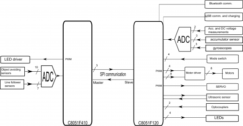
The two controller communicate via SPI interface. F410 is the master, because It send the data to the F120 controller. F410 control the LED driver for object avoiding sensors, and handle the signals from the line follower sensors, later I will explain these sensors.
The F120 controller is the brain in my bot. It has got 2 UART, PCA, 7x7 I/O port and some other good stuffs. It is a centipede, becase It has got one hundred port. This controller responsible to control the robot and also responsible for sensors and actuators.
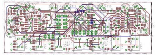
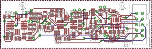
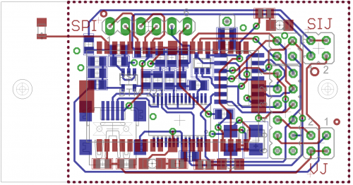
I designed five different schematics and PCB layouts for my robot, let me introduced it. This is the front and back board for my bot. It consist the line following sensors (TCRT5000) and the object avoiding sensors. The object avoidings sensors are infraled and phototransistor duo, with some electronics magic. The bot can detect the objects within 10-15 centimeter and send a signal to F410 microcontroller’s ADC unit. The F410 can handle these all sensors, and with the mode select, you can choose modes (object avoiding or line following). This controller send the information to the brain (F120) via SPI interface. Bot has got 7 line follower sensor, it is perfekt, because via SPI, I can send 8 bits, so this is a TRUE/FALSE decision and I have one extra bit. Bot has got a back board, that is similiar with the front board, but the back board only consist of the object avoiding sensors. F410 handles all front and back object avoiding sensors as well.
This little board responsible for 3-axis gyrosscopes and for the accelerometer sensor. It is connected to the F120 controller’s ports. With this, You can detect a roll, or some other stuffs with relation with moving.
This board is a motors handler board and the DC-DC converters board. This has got two L293D IC for the four DC motor. This board also handle the accumulator voltage, and set it to 6V (for motors) and 5V (for sensors). The motors ports connected to F120 board.
This little board is for UART and\or Bluetooth communication. This connected to F120 board.
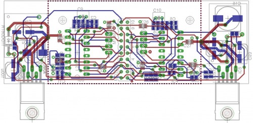
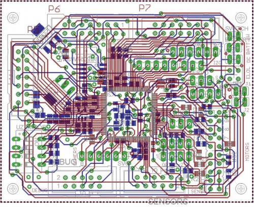
This is the bot’s main board, with C8051F120 microcontroller. It has got so many connectors to the other boards. This board consist of a accumulator charger as well, and the connectors to the optocouples, servo, ultrasonic range sensor, etc.
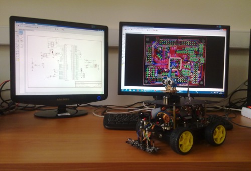
The question is now, how looks like my bot in real word!? You can see in next pictures.
For summarizing I tested the sensors, actuators, I desinged the schematics and PCB boards, I did the soldering work, I did the programming as well.
It got a new plexiglass panel, for good seeing of inner stuffs.
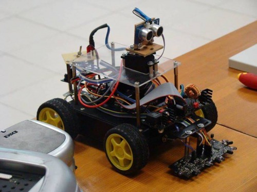
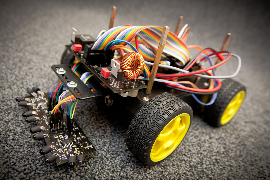
This is a promo pic about my bot, but this not consist of all boards and sensors.
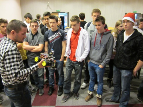
This is me, while I introduced my bot at University of Szeged, Faculty of Science and Informatics’s open day.
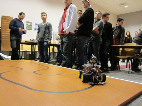
Z-bot was in action.
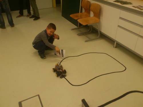
Several times, I introduced my bot, this time for Researchers’s night. I think the little kid, likes my robot.
Unfornutally, I only implemented line following mode (see in video). I also tried all sensors, but I not implemented an object avoiding mode. I implemented later an Android app for controlling the robot via Bluetooth. I also tried controlling my bot with my wheel joystick and pedals from computer with a LabVIEW program via Bluetooth (see in video). I hope it, someday I will have enough time to implement everything what I want.