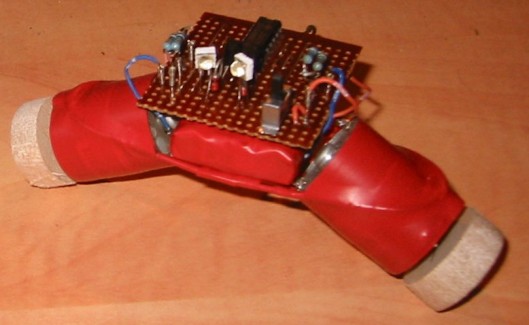
xi, the cross-eyed phototropic robot
I named the robot "xi" - pronounced "cross-eye" for reasons which may be a bit embarrassing. Having completed my phototropic robot and went to test it I discovered that the robot would run away from the light as the two motors were supposed to be connected on opposite sides of the IC, instead of re-wiring the project I twisted the photodiodes so they cross each other, giving the appearance of crossed eyes.
The robot consists of: two photodiodes (pulled from a VCR), a 7404 IC (Hex Inverter), two transistors (BC548), two diodes (scavenged from some PCB or another) and a Ni-MH battery pack from an old mobile phone. The chassis was made by soldering copper wire to the motors and provides a simple, flexible base for the bot. Two wheels made from balsa wood finish the robot. As all the parts were scavenged or found (exception of the transistors which were bought in a set) the build didn't cost anything, which was a key factor in the design as I didn't have any money for buying parts when I made this back in 2004 (poor student and all that).

Thanks to the folks who commented on this I was spurred into taking a few photos.
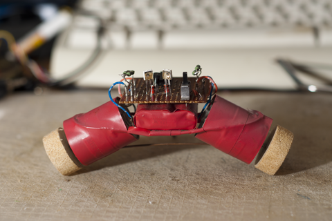
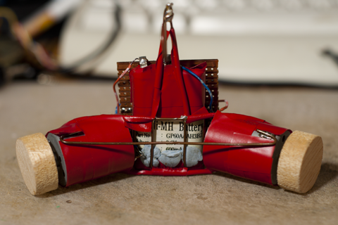
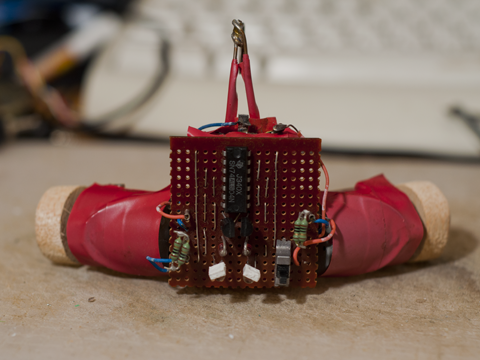
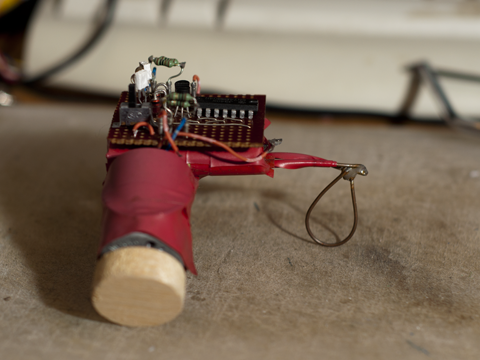
09/09/12 - Added video I made today. Sorry it took so long to get round to making it.
Heads towards brightest light source it can see.
- Actuators / output devices: 2 motors
- CPU: 7404 logic IC
- Power source: 3.6v 600mA Ni-Mh
- Sensors / input devices: 2x photodiode
- Target environment: indoor


