


Xbee controlled 5 Axis robot arm
I wanted to make an arm for my terrestrial robot V2.0 so this is it!
Parts used:
Servos:
- Turntable servo x1, 6kg/cm torque
- Base servo x2 , 10kg/cm
- Fore arm servo x1, 8kg/cm
- Wrist servo x1, 8kg/cm
- Gripper servo x1, 8kg/cm
- 6x servo horns
Materials:
- Rc Helicopter aluminium tail-boom 20mm hollow tube
- Right angled piece of aluminium 2mm thick
- Standoffs
- 3x castor wheels for turntable.
- 2x 3mm acrylic sheet for turntable top and bottom
- Power supply atleast 8A! Prefrerebly 6v 12A
- 2x Xbee 1TX, 1Rx
- 2 arduinos
This robot arm is for my robot project HERE
The roof is now on and i have also made a robotic arm for my rover. I made a simple turntable base taking idead from this fellow robot builder:
https://www.robotshop.com/letsmakerobots/6dof-robot-arm-controlled-speech-recognition-or-emg
As you can see, his is much much better! i wanted something quick and easy to make. I built mine using tail booms from my brothers old and crashed rc helicopters. They are aluminium and their structure makes them strong and they are hollow so they are very light. Another reason why i chose these alumunium rods s that they are easy to manufacture into what i want and they would weigh less than if i used acrylic to match the strength of the aluminium booms.
Update #1
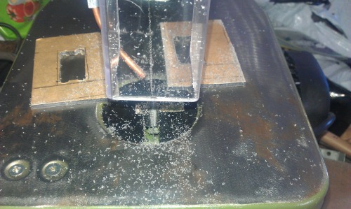
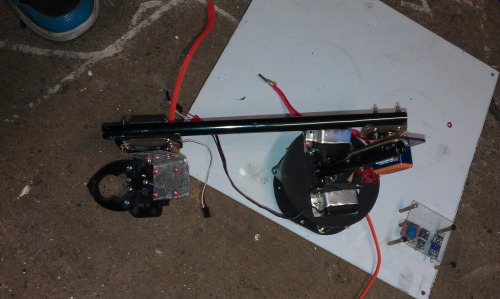
The turntable:
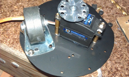
For the servo mounts i cut out the outlike of the servo using my trusty scrollsaw. and just filed it down to size. I sed 3mm acrylic so its faily strong. In hindsight i should have kept the tailboom servo mounts but i missplaced them and they got thrown out,
Stay tuned!
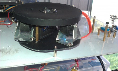
Update#2
The main servo installed. I will add a supporting braket so that the arm will be more stable.
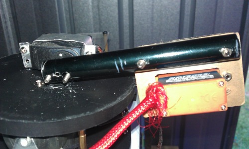
And the arm continues to grow! I test the arm in the videos at the top of the page
I am currently waiting on my gripper i purchased from sparkfun once it has arrived i will begin some more thorough testing!
Update # 3
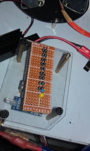
I also wanted to make an power rail for all my servos so make power connections neater and easier. I will have an 8 Amp 6V servo power supply connected to this power rail, instead of having a mess of wires. I grabbed a breadboard and some headers that i had sitting around and this is what i came up with. Its can now power 8 servos.
Stay tuned!
Update #4
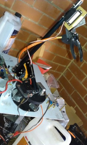
I am happy to say that the robot arm is done! The arrival of the gripper gave me the drive to finish it all off in one afternoon. Its a 5 degree of freedom robot arm and will do quite a fair bit. I have also included the videos of the arm working. Here are some pictures showing it. This is my second attempt at making a robotic arm. My first one was a basic 2 axis arm.
Another View
Stay tuned!
Prick things up
- Actuators / output devices: servo motor
- CPU: ATMEGA 2560
- Power source: 6V
- Programming language: C
- Sensors / input devices: arduino input