


Wooden Bob
UPDATE 29-SEP 2014
I'm well into programming the robot and enjoying the excitement of getting to grips with the almost finished robot.
I thought I'd post an update showing pics of how the robot bolts together...
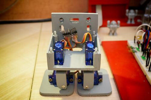
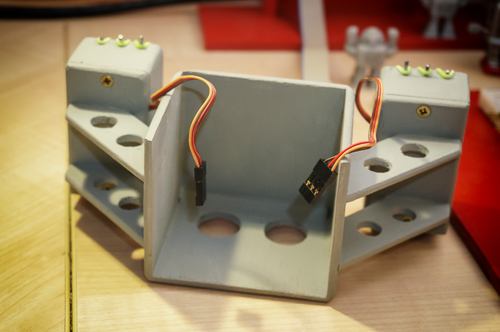
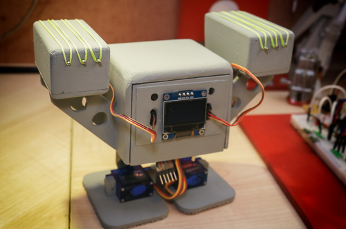
Here's the chassis with the four walking servos in place. Each pair of servos shares a four pin plug. Hot glue provides the insulation and some stress relief to the wires.
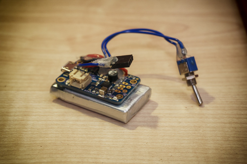
Heres the power pack. The 4.4g servos in the missile racks need 5v to pull the release pins nicely so I got this AdaFruit PowerBoost 500 charging circuit to go with my LiPo cell. The power and battery voltage low wires are presented as a 3 pin socket. The USB charging socket is accessible at the front and the switch is tucked round the back.
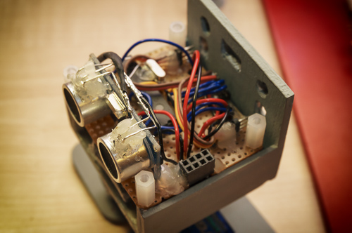
The underneath of the main board. The 3 pin plug that goes to the power pack can be seen with the 5 pin in circuit programming plug behid it. In between the two plugs is the two row header socket that the servo plugs go in to.
The main board tightened down with four plastic hex spacers. The placement of the battery and charging socket can be seen.
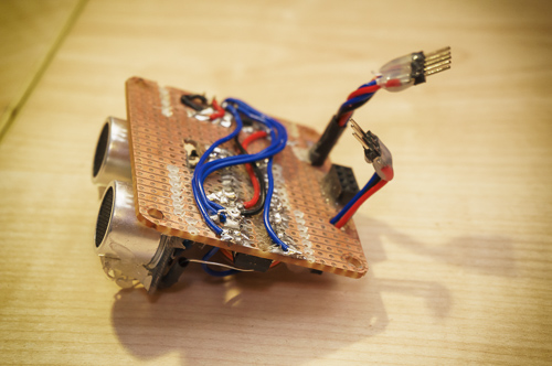
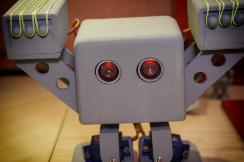
The mess of hot glue and wires around the HC-SR04 is wher I have cut into the sensor cans with a dremel and inserted Red/Green LEDs into each eye. The idea being to get the eyes lit up with reflections of the shiny bits. A delicate operation but it works and the sensor tested fine on the breadboard afterwards.

The PIC 18F2620 is a bit buried here. Its running at 25Mhz and with 64K of program memory I'm hoping to have a lot of fun developing some cool moves for him. The header socket which connects to the top deck can be seen in the foreground.
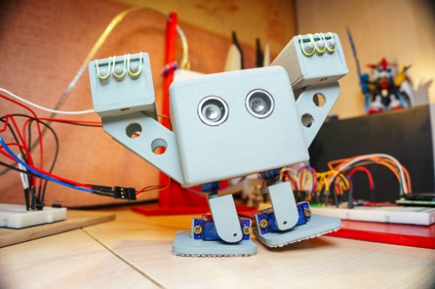
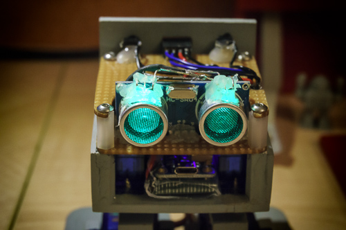
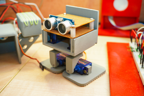
Top deck screwed on and the eyes lit up green. In the background you can see the socket for the OLED screen and the hot glued backs of the the two push button that make up a go-pro style interface for Bob. I spent a while getting the LEDs lined up and the pic doesn't do it justice, in real life Bob doesn't look like he has a lazy eye.
The inside of the shell and underneath the missile racks. It's just a push fit on the chassis.
Peek a boo!
The back of Bob showing the OLED screen and two button interface. The missile rack servos plug into pins on the main board back here. Poking out of his butt is the five pin programming interface, when the coding is done I can tape the pins and the plug will stow inside out of the way.
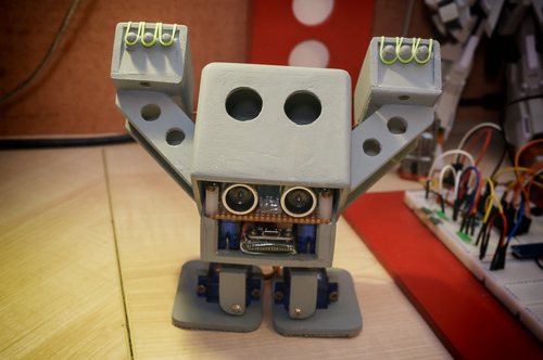
I think Bob looks great with eyes that are flush to the face, but that's just me. Watch out! Red eyes is a sign thayt Bob is in attack mode and is about to launch missiles!
Almost build complete, some tidying up to do a nice colour scheme and an IR sensor to detect targets... Thanks for reading.
An update with a video to follow in a week or two...
UPDATE 14-SEP 2014
My first video! I'll try and find a link so I can put the LMR logo on it, I did have a quick look but couldn't find something I could download. I'll have more time to look for next time - if anyone can help with a link it'd be appreciated. The music in the video is from a Japanese robot show from the 70s that I liked.
I've used an Arduino to trigger the pods for the video and it fires them off in full automatic mode as long as I hold the button down. The finished robot will be able to shoot single shots.
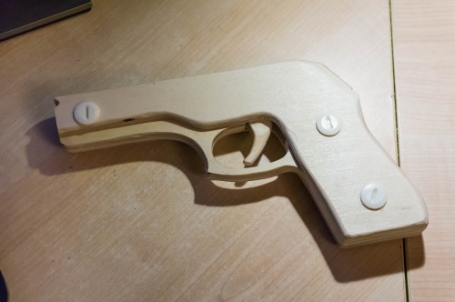
Making the rubber band gun made me think about making my Bob shoot a salvo of rubber bands. I had two old 4.4g servos from lightweight model aircraft and figured they could be made to actuate a simple sliding pins rubber band launcher. The bands are 'loom bands' I guess all countries have these, they've been a craze in the UK this summer. Small ruber bands you can loop together to make bracelets and models.
With Bob now being armed, the red paint had to go. Also I noticed I hadn't got as good a finish on the balsa as I was expecting, so here Bob is in a grey primer, I'll rub him down and get a smoother finish. I think the final scheme and style will be of the SD type Japanese mecha.
I have ordered a 600mAh LiPo that will fit between the hip servos and I am sure I can get all of my electronics to fit..
One thing I have tried is to glue 'non slip mat' to his feet, this is a textured rubber roll you can get in the cheap shops in the UK. I'll do a picture some other time when I know it does or doesn't work. At the moment I'll say that it looks like this matting on the feet will improve things, but then I'm a noob and its a great big learning curve for me.
I have not done anything with the mouth of Bob yet. I am sure I can get Bob to shoot when there is something at a set range of the ping range finder, I even think I can get Bob to pivot slightly to aim a missile at a target directly in front of Bob. (Originally the missile pods were going to be set toed in to converge at a set range, but it looked odd). I wondered if the mouth could be some kind of IR sensor and I would create lightweight knockdown targets that are illuminated with IR. Very ambitious for me, but it's something to 'shoot for'. So for now I haven't made a mouth feature.
Software wise, I have an interrupt driven scheme that allows the servos to move slowly and smoothly. TMR0 is set to trigger 3 times 3ms apart and then a fourth time 11ms later. In total this is 20ms and each servo gets a pulse every 20ms. When the TMR0 fires the code calculates the required pulse for the current servo and loads up the TMR3 registers with the required values to generate the pulse. I didn't quite get the Ping sensor working in the 8ms gap the servo control scheme leaves but I did experiments before that lead me to think that 8ms is pleanty. Bob isn't a stabilised gun platform and he won't be firing on the move, so the two servos in the rocket pods will be triggered when he's stopped and I'll pause the TMR0 to make life easy for myself.
With the OLED screen and a two button GoPro like interface to add to the back, it will be cramped, but with patience I am sure it'll fit... I think...
UPDATE 07-SEP-2014
The feet, legs and base are complete and have been sprayed a shiny red. My first oversight has reared its head, the Li-Po cell I have bought is 65mm long, which won't fit nicely into a Bob head. My decision for now is to just build a platform with legs and get on with the programming of the servos. I would have got a lot further today, but one of my sons wanted to build a step up action 3 shot rubber band gun. Sorry to post a non-robot pic, but I'd like to set a standard of posting a pic with every update and I didn't take any pics of the Bob parts (that pic to follow in the week).
Hello, my first post and first attempt at a robot. I visited the Manchester (UK) Mini Maker Faire recently and saw some biped robots and I decided that I just had to have a go myself!
I've made radio controlled cars boats and planes all my life, in the last few years I've been interested in microcontrollers and my day job is as a software developer. Making a robot seems to be a challenge that brings together a few interests and I expect to have a lot of fun.
For my first biped robot I'm being cautious with how adventurous I'm going, I've choosen to make a Bob. Apart from the fact I think it's aesthetically nice, this suits me because its a biped that uses 4 servos and not having access to a 3D printer it's quite a simple thing to create using my normal modelling skills.
My first goal was to be sure I could get the microcontroller side of things together and working before I started building the robot itself. One of the challenges of Bob for a noob seems to be the smallish volume available to stash all of the stuff in neatly.
So the first thing was choosing the brain power, a few years ago I looked around at different options and settled on the Pic microcontrollers. There is such a wide range to choose from and you can always start with a bare chip and work from that. I completed a packaged assembler programming course but once I got an understanding of Pics I choose the MikroC compiler which in tandem with their programmer does the job very conveniently for me.
I have limited space indoors for doing my electronics and playing around with the coding so I've taken some time to make a stand for my MikroProg programmer and made a few boards that have these incircuit programmer headers and a socket for a bench power supply. Sprayed up in the bright red of MikroElektronika it doesn't look a complete eyesore to my wife.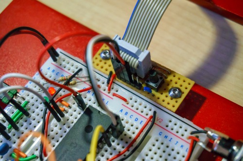
Being able to step through code at run time is excellent but often I've found having some way of writing out state is very useful. I will happily give one pin to have a led blink to show me the main loop is running and for my breadboarding projects there has always been an LCD.
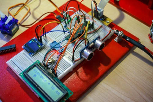
With the 4bit LCD interface I loose 6 pins to the LCD which has always been fine and over a few years I've collected a few 2 and 4 line LCDs that work with the mikroC libraries very easily. I wanted some kind of display on my Bob and realised that a chunky big LCD wouldn't fit. Also I will be using a smaller 28pin chip for Bob and something that uses less pins would be better.
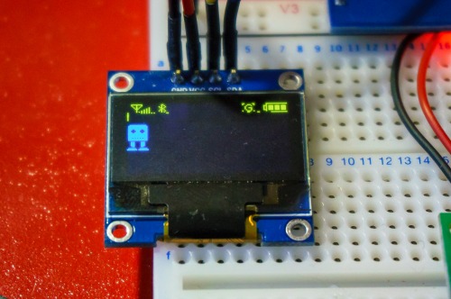
I saw these little OLED screens on ebay costing around £3 with I2C interfaces and bought one not expecting too much. Actually I've been very impressed with it (and ordered a few more). Even with my progressing years the screen is very easy to read and programming it not too difficult. This is the two colour yellow/blue one, I've left some junk from the demo code for it across the top to illustrate the colours. My little Bob graphic will have bars to his right indicating the range to an obstacle. In my mind he'll have two walking speeds and some kind of row of icons in the yellow bit to give an outward clue as to what he's thinking. Ample room at the bottom for debug messages and info about the servos.
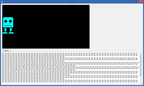
I made a quick application to create the data for any graphics I want to display on the screen. Because of the size of it and the fact it will be on the side of a hopefully moving biped I'll sidestep the issue of fonts this time round and just use icons and bars for everything I need to output.
A quick overview of the code. I've got most of it working on an 18F4520 but it'll run on a 28pin 18F2620 in the robot:
Timer0 - provides a 20ms interrupt that tells Timer1 to start. Timer1 will control the 4 servo pulsewidths. Timer3 times the Ping sensor echo pin and I am using an on change interrupt from the echo ping to start and stop the timer.
The Ping is working great, I used the information and some of the code from here. The code there does not reset the Timer registers after using the them to calculate the distance and I found needed to add that code to get it all working for me.
I've only got code in for two servos, it took me a long time to understand controlling servos using intterupts rather than delays. All my own code I didn't immediately find a library that I liked. I do have to credit this series of articles though as they have helped me a lot.
The next step is to build Bob, I'll build mine from balsa wood. I got the stl files and converted them for use in Sketchup for where I could tape measure the parts to get dimensions. If you got this far, thanks for reading.