


Wirelessly Controlled 3D Printed Hand
Part 1: Project Proposal
This project was the second project that I did at Boca Bearings for my internship. The details and the steps of how I carried out this project can be seen at the company's blog at http://bocabearingsworkshop.blogspot.com/search/label/3D%20Printed%20Robotic%20Hand.
Boca Bearings is currently holding a Innovation Contest where you can submit your project and can win a 3D printer or a GoPro camera. The grand prize is $5,000. The check rules and entries, visit http://www.bocabearings.com/innovation-contest/.
The Boca Bearing company sells many kinds of bearings in many different types of sizes. From miniature bearings to bearings for industrial uses. Boca Bearings carry bearings for robotics and for RC vehicles. The company's website is http://www.bocabearings.com/default.aspx
Purpose/Goal:
The purpose of this project is to learn to use a 3D printer and to further my skills in using the Arduino. My goal is to have a functional hand that will mimic my hand movements through the use of a glove with flex sensors attached to it. The robotic hand will be assembled out of 3D printed parts from files that were obtained from an open source project called InMoov.

Initial Design Concept:
The design of the hand is already pre-made from the project InMoov that provides all the 3D printable files. The other part of this project would be just a glove where I will attach flex sensors and a LilyPad Arduino placed on top of the glove.

Materials:
Glove; about $5
5 4.5 inches flex sensors for the fingers, $12.95 each from Sparkfun.com
A LilyPad Arduino Board with 6 analog inputs, $19.95 from Sparkfun.com
A LilyPad FTDI adapter to program it, $17.95 from Sparkfun.com
A XBee module for radio communication, $24.95 from Sparkfun.com
A LilyPad XBee shield to connect the XBee module, $14.95 from Sparkfun.com
5 47K ohms resistors, can get some for free from my school.
Battery Pack for 3 1.5V batteries with switch, $1.95 from Sparkfun.com
List of materials for the robotic hand:
3D printed hand from files, free
An Arduino Uno, have one already from previous project.
Another XBee Module, $24.95 from Sparkfun.com
5 Servos, TowerPro SG90, $22.63 with shipping from shopshiphappy.com
Or approximately $15 from dx.com
A Servomotor Shield, $17.5 from Adafruit.com
A shield to connect the XBee module for Arduino Uno, $14.95 from Sparkfun.com
Fishing wires to connect the servos to the fingers, find some lying around
A 9V battery, find one lying around.
Budget:
For the budget, I found all the prices of the parts for this project and decided to mostly find them from Sparkfun.com to lower costs of shipping and to probably create an account to possibly save money. I am going to get the servo shield from Adafruit.com. The total costs of the parts listed above will be $229.53. This cost could possibly increase a little more because shipping charges from Adafruit.com for the servo shield. Shipping will be free from Sparkfun.com because shipping is free for orders over $75.
Timeline/Delivery Dates:
After getting all the parts I will try my best to work on it. It will all depend when the parts will arrive. If all the parts that I ordered from SparkFun.com come first, I will be able to work on the glove part of the project since all the parts necessary for the glove will be coming from Sparkfun.com. The servo shield and the servos will come from different places so I will not know if they will come first before the parts from Sparkfun.com. The amount of time I think I will take to work on this project will be about 2 months to be conservative. While I wait for parts, I can start typing up the code for the LilyPad on the glove and the Arduino for the robotic hand. I still have to print 3D parts of the hand so I can do that do while I wait for the parts. But my main goal is to finish as soon as possible to bring more content and to start on a whole new project that will possibly include the use of bearings.
Part 2: The Pre-Build
Design:
For the design of the robotic portion of this project I will be using a 3D printed hand that was created by InMoov. InMoov is a open source 3D printed life size robot. The link to their website is:
InMoov provided the 3D printed files that I am currently in the process of finishing printing. The color I used for the hand will be glow in the dark green since it was the most abundant of PLA that was in stock here at Boca Bearing. I still have some more parts that I need to print. At the moment the 3D printer is down due to connection issues but should be fixed soon.

To control the robotic hand I will be using a regular glove that I will be getting soon probably from Wal-Mart. The glove doesn't have to be special. It just has to be fabric and have space where I can sow the flex sensors and the LilyPads onto.
Materials List and Cost:
As mentioned in the previous phase, I have compiled the list of the materials that I will be using for this project. The parts that I ordered from SparkFun.com are the following: 5 4.5 inches flex sensors for the fingers, $12.95 each, to detect when the hand is being closed in a fist or open.

A LilyPad Arduino Board with 6 analog inputs, $19.95, to program it with the flex sensors. And a LilyPad FTDI adapter for $17.95. Without the adapter, I won't be able to program the LilyPad.

2 XBee module for radio communication between the robotic hand and the glove, $24.95 each.

A LilyPad XBee shield to connect the XBee module to the glove, $14.95.

Battery Pack for 3 1.5V batteries with a switch integrated in the case, $1.95. This will provide the power needed for the LilyPad.

The total cost for the parts from SparkFun was $166.45 with free shipping. I no longer order the shield to connect the xBee to the Arduino since I will be making my own to make sure everything will fit together.
From AdaFruit.com I ordered the Servo shield for $24.46 with shipping. This shield has the capability to control 16 servos. The motor shield that I used for the line follower could only control 2 servos, which isn't enough. As you can see in the pictures, I have to solder some of the parts onto the shield. I think I might also need to order some headers to stack the shield right on top of the Arduino Uno.

From Amazon.com I ordered 5 TowerPro servos for $13.80 with free shipping. Here is a photo of the servo I ordered. I still haven’t actually received them yet so I couldn’t take a picture of them yet.

The total cost so far came out to $204.71 which is less than $229.53 that was anticipated in costs. I saved some money by going with smaller servos since I thought I might not really need strong servos. I also decided not to get the Arduino XBee shield since I can make my own out of a perforated board.
Purchasing:
For all the parts that I ordered, I had them delivered to Boca Bearings where I will be completing this project. Boca Bearings is covering the costs for the parts of this project.
Receiving:
So far I have received all my parts except for the servos. I am still waiting on the servos to come. All the parts that I ordered from SparkFun.com came in a small red orange box.

I was surprised that the box was small. I was anticipating a larger box. But everything I ordered from SparkFun.com came in perfect condition with no damage to the parts. The servo shield from AdaFruit.com came in a parcel package.
Documentation Plan:
My plan for documentation will be the same as before for the line follower robot. I will take pictures of everything that I am working on as I go. After completing a part I will then do the write up on how I made that part. Maybe this time I will also be taking some videos of me completing the project. I will soon work on the making of the glove soon since I have all the parts. I just need to get some resistors from my school and a glove then I will be ready to go.
If you have any questions or would like to know anything about the setup, just drop a comment and I'll try to get back to you as soon as possible.
Part 3: The Glove Build
In this part I will be going over in the making of the glove that will control the 3D printed hand. I started off by first soldering the 5 47K ohm resistors onto the LilyPad's pads a0, a1, a2, a3, and a4. I also soldered the resistors together as shown in the picture below.

From there I went ahead and started to create holes at the top of each flex sensor by using a needle. I will be sowing through this hole to the glove to create a good attachment to the glove.

After doing that, I went ahead and started sowing the flex sensors onto the glove that I got from Wal-Mart. I sowed where the fingers bend. I learned that if you don't sow it down enough that the sensors will sometimes not go back to being straight flat on the glove. I also sowed the LilyPad onto the glove. But I later cut the threads attaching the LilyPad because I needed some rearrangements of the parts.

I then proceeded with adding wires to make connections between the flex sensors and the LilyPad.
I used red wiring to connect the power pad from the LilyPad to the pinky flex sensor. From there I connected every right pin of each flex sensor together. I used yellow wires to connect the left side connection of each flex sensors to the analog pads. Every time the flex sensors are bending, the resistance will change and that will be read by the analog pins. At the end of the connections of the resistors, I connected a black wire between the last resistor and the negative pad on the LilyPad for ground.

I then went ahead and started working on the LilyPad XBee shield. I just soldered a red and a black wire on the power and negative pads of the shield. I then added two yellow wires that I soldered on the tx and the rx pads. These two yellow wires will be connected to the LilyPad's rx and tx pads. From rx to tx and tx to rx.

I was running out of room on the glove so I decided to place the XBee shield in between the flex sensors and the LilyPad. A gauntlet style glove would be more ideal since you would have more room to place the components onto. I didn't really thought I would need more space but I was wrong.

I put more threads on the flex sensors to make it more secured. I also added electrical tape on the XBee shield where I see there could be some sort of short circuiting or any type of unintended connections between the shield and the flex sensors. I also soldered the battery pack on the positive and the negative pads of the LilyPad as shown below.

So that's pretty much it for the glove. I'm currently working on assembling the 3D printed. I will have more on that once I have finished assembling the hand.
If you have any questions or would like to know anything about the setup, just drop a comment and I'll try to get back to you as soon as possible.
Part 4: The 3D Printed Hand Build
In this part I will be going over in the building of the 3D printed hand. You can find the files from inmoov.fr. Inmoov is an open source 3D printed life size robot where you can print various parts of a robot. Here you can find the files to print the hand. I also found an instructable on instructables.com that has the files already ready to just download and print.
http://www.instructables.com/id/DIY-Robotic-Hand-Controlled-by-a-Glove-and-Arduino/
I started by printing the smaller prints at a few files at a time.

A printout of a finger and circular horns for the servos
I also separated the prints in ziploc bags to avoid confusion between the fingers since the fingers seem to be almost identical. I didn't want to mix up the pieces and create irregular fingers.


During the printing of the smaller pieces, I was working on the glove portion of this project. For the bigger parts of the robotic hand, I printed them overnight at Boca Bearings. I just started the prints before leaving for the day and hope that they will be done by the next morning. Sometimes that doesn't happen. Like when I printed several big pieces together such as in the picture below.

Parts of the arm
After having printed all the parts, I had to remove some supports that were printed on the parts. Some of the supports were fairly easy to remove but there were times where they were very difficult to remove. So I sometimes used a dremel tool get some of the supports off.

Since the dremel operates at high speeds, the PLA would heat up and deform. This created a problem with the fitment of some of the parts. To solve this I would sometimes use a file to remove some of the buildup that happened at the edges of the parts. I then started on assembling the hand. I started off by gluing the parts of one finger. The glue I used was epoxy glue for plastics by LocTite. There were instructions and diagrams of how they should be assembled on inmoov.fr. The fingers required me to file each part so the finger can move smoothly at each joint. Basically at every joint I had to file away some PLA to make the parts fit perfectly. I had to do this for every finger and for every part that you see below.


I used 2mm machine screws and nuts to keep the parts together at each joint of the finger. The holes of each piece were initially to small to fit the screws so I used Boca Bearings RC Tool Kit to make the holes bigger.
http://www.bocabearings.com/productdetail.aspx?ItemID=24674

I used the 1.5mm tool to create a 1.5mm hole. Then I slowly increased the hole size with the 2mm tool. While I was making the hole at the top joint piece of the pinky finger, I didn't provide enough support to withstand the force of the tool so I ended up breaking it. So I decided to print another pinky to replace the broken part. I didn't notice that the PLA color in the 3D Printer was changed so I ended up printing a white pinky replacement.

Afterwards, I finished up the hand except the finger tips. I didn't glue the finger tips at this time because I needed to run string through the fingers towards the top and then glue the finger tips. Before I do that I had to use some bolts to keep the pinky, ring finger, and thumb attached to the hand. The bolts were provided by inmoov.fr.

I found that the bolts that I printed were to big to run through base of the thumb, pinky, and ring finger. So instead of using the file to file away some PLA, since it's very tedious and time consuming, I just decided to remake them in Solidworks. The shape of the bolts are really simple to make so it didn't take much time. Here's a comparison of the bolt that I made with the original bolt.

I used some epoxy glue to hold the bolts in. Afterwards, I went ahead and started to run string through the fingers. I got some fishing string from Jeff here at Boca Bearings.

Each finger needed two strings: one to close the finger and the other to open it. Each string I used was about 75cm long. This part was very time consuming.

Once I had all the strings running through all the fingers, I tied a knot at the top of the finger for each string. I didn't get to take a picture of this since I was in my "zone" and forgot to take pictures along the way. I also forgot to take pictures at different parts of the project. I then glued each finger tip on. Then I decided to attach the hand with the wrist by using one of the 3D printed bolts. This is what the hand looked like so far.

I then went ahead and started working on the servo bed for the robotic hand. The servo bed was intended for average size servos but I bought smaller servos, the TowerPro micro servos. So they didn't fit perfectly snug in the servo bed. Instead, they would just move around everywhere. So I just did some measurements of the servo bed and of the micro servos to find out how much space I need to fill with some more PLA. Instead of reprinting the servo bed with modifications, I decided to just add some blocks that I will be able to glue on the servo bed.

In the picture above, I made the blocks in Solidworks. I measure how thick the blocks should be to be able to fit the servos snugly. I also created holes were the servos will be screwed into with 2mm bolts. I glued the blocks into the servo bed and added the five servos in.

What I forgot to do, when I made the blocks in Solidworks, was to create holes in the block so the servo wire can run through the bottom as shown in the picture above. So I just used the dremel to cut some holes. I also forgot to account for the protrusion of the wires towards the bottom of each servo.So it was to tight for the servos to initially fit in. But with some filing I manage to get them fit nice and snug. I then added the horns for each servo.

I then filed the two pieces of the bottom side of the arm and then glued them together. Once the glue was dried, I glued the servo bed inside the forearm.

By now, I realized that the horns of the top three servos would interfere with each other. This would cause problems during the operation of the fingers. I later on decided to cut the horns since I wasn't going to use the outer holes of the horns. I compared the horns to the servo horns that I printed. I found that the the third hole from the center lined up with the holes of the 3D printed horns. So I decided to cut off the fifth hole. For the middle servo I also cut off the fourth hole to be able to fit the three servos.

Then it was time to attach this portion of the arm to the wrist. I had to do some filing again to make it fit well.

Around this time, one of the strings in the pinky finger was pulled to hard that it went through the whole hand and out. That meant that the knot I had tied wasn't big enough to not fit through the holes where the string runs through. So I had to remove the tip of the pinky finger to be able to retie the string again. Luckily, I still had the remaining pieces of the pinky that I printed when I broke the pinky piece. So I ended up with a white pinky. I then started to add the hand covers and the finger covers on top of the hand as shown below.


I used the same size screws that I used for the fingers. But sometimes those screws were too long so I ended up using some short screws that I found lying around. I then went ahead and started to tie the strings onto the horns of the servos. I used hot glue to keep the strings on the horns. I decided to test the servo horn versus the 3D printed circular horns.

In the end I decided to use the servo horns since it seem to operate the pinky well. I also decided to use the servo horns because of the code that I was going to use. The code that I am going to use is from this instructables
http://www.instructables.com/id/Wireless-Controlled-Robotic-Hand/
I followed his procedure in how to tie the strings on the servo horns. I also didn't used the circular horns since there was no space in the 3 servo section of the bed. I then went ahead and started to tie the strings to each horn. I would turn the servo clockwise until its final position. Then I would pull on the closing string until it closes the finger. Then I hot glued the string onto the horn. I then turned the servo all the way onto its other end. Then I pulled on the opening string and hot glued it on the horn. While I was doing the thumb, I accidentally pull one of the strings too hard and broke the string.

So I decided to do some googling to learn how to tie two fishing strings together.So I learned how to tie a uni-knot and tied a uni-knot on the broken string.

I hope this won't affect its performance. It took some time in getting the strings in the right position of the horns and trying to avoid tangling the strings. But I eventually finished doing all the strings.

I noticed that there was some issues when turning the servos by hand. The pinky worked fine. But some of the other servos wouldn't either close a finger all the way or open the finger all the way. Since I used hot glue, I can just reapply heat and try to calibrate the strings again. Sometimes, one string wouldn't let the other string do its job. It was as if the strings were to tight. I think the solution to this would possibly be by using a more outer hole of the horn to allow more movement. I will do this later on after I have done the programming. I went ahead and started to work on the electronics portion of the hand, like the shields and the Arduino Uno.

I ended up ordering an XBee shield from sparkfun.com for about $15. I also ordered stakable headers from them and ordered an Arduino Uno clone from 16Hz on ebay for $15. I had to solder on the stackable headers on the Adafruit Servo shield and the XBee shield. Also for the servo shield, I had to solder on the pins for the connections of the servos and the power block. I started soldering the headers on the servo shield by putting the shield upside down on the headers.

I did what I did before for the motor shield for the line follower that I made. You can check it out on here on this blog. I just soldered one pin of each individual header. Then I check if it lines up well with the headers of the Arduino by checking if it stacks into place. I had to reheat one header to readjust it. Afterwards, it was good. Then I continued to solder the rest of the pins onto the shield. I then soldered on the servo pins and the power block. I repeated the same for the XBee shield. The final work looked like this:


I then went ahead and tested the shield with one of the servos of the robotic hand. I uploaded an example from the shield library to test the servo. Here's a quick video of it being tested.
If you have any questions or would like to know anything about the setup, just drop a comment and I'll try to get back to you as soon as possible. And if you have any suggestions, just drop a comment.
Part 5: Programming and Debugging
Now that I have finished building the hand and the glove, it was time to start writing the programs for the hand and glove. For the glove, I simply just used the code from an Instructables. It was created by Gabry295. The link to the instructable is:
http://www.instructables.com/id/Wireless-Controlled-Robotic-Hand/?ALLSTEPS
There you can find the code for the glove. I went through a few variations of the code but I just eventually just kept the code the way it was. The code is as follows:
/*
Flex Glove
Created by Santin Gabriele, 2014
I.T.S.T. "J. F. Kennedy", cl. 5^A EA
Thanks to Elias De Lamper for suggestions to improve this program!
*/
int ResThumb = A4; // Variables of the analog read form the flex sensors connected to the
int ResIndex = A3; // analog pins of Arduino LilyPad
int ResMiddle = A2;
int ResRing = A1;
int ResPinky = A0;
int OpenedThumb =0; // Variables of the values when the hand is completely opened
int OpenedIndex =0; // This is needed for a continuous calibration
int OpenedMiddle =0;
int OpenedRing =0;
int OpenedPinky =0;
int ClosedThumb; // Variables of the values when the hand is completely closed
int ClosedIndex; // We can't set it to zero since that the minimum value reached
int ClosedMiddle; // in the analog read never reach zero. We'll assign the value of
int ClosedRing; // a first analog read, then the program in the loop will
int ClosedPinky; // automatically assigning lower values
int thumb =0; // Variables of the values to send
int index =0;
int middle =0;
int ring =0;
int pinky =0;
void setup()
{
Serial.begin(9600); // Activating serial communication, XBee Series 1 are pre- // programmed at 9600 baud/s
pinMode(ResThumb, INPUT); // The variables of the sensor are set as input
pinMode(ResIndex, INPUT);
pinMode(ResMiddle, INPUT);
pinMode(ResRing, INPUT);
pinMode(ResPinky, INPUT);
ClosedThumb = analogRead(ResThumb);
ClosedIndex = analogRead(ResIndex);
ClosedMiddle = analogRead(ResMiddle);
ClosedRing = analogRead(ResRing);
ClosedPinky = analogRead(ResPinky);
}
void loop()
{
thumb = analogRead(ResThumb);
index = analogRead(ResIndex);
middle = analogRead(ResMiddle);
ring = analogRead(ResRing);
pinky = analogRead(ResPinky);
if(thumb > OpenedThumb) // Calibration reading and setting the maximum values. This needs you to completely open your hand a few times
OpenedThumb = thumb;
if(index > OpenedIndex)
OpenedIndex = index;
if(middle > OpenedMiddle)
OpenedMiddle = middle;
if(ring > OpenedRing)
OpenedRing = ring;
if(pinky > OpenedPinky)
OpenedPinky = pinky;
if(thumb < ClosedThumb) // Calibration reading and setting the minimum values. This needs you to completely close your hand a few times
ClosedThumb = thumb;
if(index < ClosedIndex)
ClosedIndex = index;
if(middle < ClosedMiddle)
ClosedMiddle = middle;
if(ring < ClosedRing)
ClosedRing = ring;
if(pinky < ClosedPinky)
ClosedPinky = pinky;
// The analog read has to be readapted in values between 0 and 180 to be used by the // servomotors.
// The minimum and maximum values from the calibrations are used to correctly set the //analog reads.
thumb = map(thumb ,ClosedThumb ,OpenedThumb ,0,180);
index = map(index ,ClosedIndex ,OpenedIndex ,0,180);
middle = map(middle ,ClosedMiddle ,OpenedMiddle ,0,180);
ring = map(ring,ClosedRing,OpenedRing,0,180);
pinky = map(pinky ,ClosedPinky ,OpenedPinky ,0,180);
Serial.write("<"); // This character represent the beginning of the package of the five // values
Serial.write(thumb); // The values are sent via the Tx pin (the digital pin 1)
Serial.write(index);
Serial.write(middle);
Serial.write(ring);
Serial.write(pinky);
delay(50);
}
This code worked pretty well for the glove. I did a Serial.println of the thumb, index, middle, ring, and pinky values to check if the numbers made sense. I tested it by wearing the glove and opening and closing my hand and checking if the those values change. It did, so I knew the code was working properly.
For the robotic hand part, I had some difficulties trying to get it to communicate with the glove. At first, I assumed that it was receiving some kinda of data from the glove so I decided to Serial.println the values that it was supposed to receive. But doing this and checking the values in the serial monitor in the Arduino program, I got nothing. Nothing popped up or any kinda of random values or letters. So I thought to myself that it wasn't working or maybe that the servos didn't work.
But to test the servos, I decided to run one of the examples of the servo shield. The example was called servo. I uploaded it to Arduino. When uploading, I have to have the xBee's off or the upload would not complete. After uploading the example, the servos would go to its minimum position to its maximum one at a time. So now I knew my servos were working.
So I went online and started to look up how to make sure the XBee's were communicating. After spending some time learning about the XBee's, I decided to check the product page of the XBee shield that I am using on Sparkfun.com. They had a guide on https://learn.sparkfun.com/tutorials/xbee-shield-hookup-guide?_ga=1.257884875.17886098.1427765704
There I learned that the XBee shield had a serial select switch at the bottom left.

So I just simply switched it to the UART side and the XBee starting to receive data from the glove's XBee! So now I was getting some kind of data from the glove. The next step was to make the servos move in response to the movements of the fingers of the glove.
The hand program from Gabry295 didn't work for my robotic hand.I figured that it had to do with the shield that I am using. I am using the Adafruit PWM/Servo shield. The command servo.write(angle) was not working for my servos. So my next step was to research servos and PWM (Pulse Width Modulation).
I went online and tried to learn what PWM was and how it worked. I found it difficult to understand it by just reading about it. So, I just decided to look over Arduino codes that used PWM to control servos. After many trial and errors, I came across just a few codes that implemented PWM. But from those codes, I learned a little more about PWM and how to include it in your program. I came across a program from:
https://solderspot.wordpress.com/2013/12/19/adafruits-servo-shield/
that uses the following function:
void setAngle(int channel, int angle)
{
// 4096 ticks is 20,000 us
// Angle 0 is 1000 us
// Angle 180 is 2,000 us
long ticks = ((1000L + 1000L*angle/180L))*4096L)/20000L;
// update the servo channel with the new pulse
pwm.setPWM(channel, 0, ticks);
}
This function converts angles to "ticks" that the servo can be set to by using the command pwm.setPWM(channel, 0, ticks). I decided to include this in my code, well in Gabry295's code. So after trying different ways to make the hand move, I ended up with the following code:
/*
Robot Hand
Created by Santin Gabriele, 2014
I.T.S.T "J.F. Kennedy", cl. 5^A EA
Thanks to Elias De Lamper for sugestions to improve this program!
*/
#include <Wire.h> // Library needed to use function for servomotors
#include <Adafruit_PWMServoDriver.h>
Adafruit_PWMServoDriver pwm = Adafruit_PWMServoDriver();
//Assign the servos to a specific channel
int servothumb = 5;
int servoindex = 4;
int servomiddle = 3;
int servoring = 2;
int servopinky = 1;
byte startPackage; // Variable that will contain the character of start package set in Glove //sketch, "<"
//int pulseconstant;
int AngThumb = 0; //Variables with the values for the servomotors (between 0 and 180)
int AngIndex = 0;
int AngMiddle = 0;
int AngRing = 0;
int AngPinky = 0;
void setup()
{
Serial.begin(9600); // Serial communication is activated at 9600 baud/s
//pulseconstant = (1000000/60)/4096;
pwm.begin();
pwm.setPWMFreq(50);
Serial.println("Ready to receive.");
}
void setAngle(int channel, int angle)
{
// 4096 ticks is 20,000 us
// Angle 0 is 1000 us
// Angle 180 is 2,000 us
long ticks = ((1000L +(1000L*angle/180L))*4096L)/20000L;
//ticks = map(ticks,204.8,409.6,200,1200);
//long ticks=map(angle,0,180,150,600);
// update the servo channel with the new pulse
pwm.setPWM(channel,0,ticks);
}
void loop()
{
if(Serial.available()) { //Waiting for data incoming from the other XBee module
startPackage = Serial.read(); //The first value will be "<", the other are assigned to the finger
AngThumb = Serial.read();
AngIndex = Serial.read();
AngMiddle = Serial.read();
AngRing = Serial.read();
AngPinky = Serial.read();
//AngThumb=map(AngThumb,0,180,150,600);
//AngIndex=map(AngIndex,0,180,150,600);
//AngMiddle=map(AngMiddle,0,180,150,600);
//AngRing=map(AngRing,0,180,150,600);
//AngPinky=map(AngPinky,0,180,150,600);
if(startPackage == '<'){ // Verifying that the first value is "<"
Serial.println(AngThumb);
Serial.println(AngIndex);
Serial.println(AngMiddle);
Serial.println(AngRing);
Serial.println(AngPinky);
//if(AngThumb<180)
//ServoThumb.write(AngThumb);
//thumbr.write(AngThumb);
setAngle(servothumb, AngThumb);
//pwm.setPWM(servothumb,0,AngThumb);
//if(AngIndex<180)
//ServoIndex.write(AngIndex);
//servoWrite(2,AngIndex);
//indexr.write(AngIndex);
setAngle(servoindex, AngIndex);
//pwm.setPWM(servoindex,0,AngIndex);
//if(AngMiddle<180)
//ServoMiddle.write(AngMiddle);
//servoWrite(3,AngMiddle);
//middler.write(AngMiddle);
setAngle(servomiddle, AngMiddle);
//pwm.setPWM(servomiddle,0,AngMiddle);
//if(AngRing<180)
//ServoRing.write(AngRing);
//servoWrite(4,AngRing);
//ringr.write(AngRing);
setAngle(servoring, AngRing);
//pwm.setPWM(servoring,0,AngRing);
//if(AngPinky<180)
//ServoPinky.write(AngPinky);
//servoWrite(5,AngPinky);
//pinkyr.write(AngPinky);
setAngle(servopinky, AngPinky);
//pwm.setPWM(servopinky,0,AngPinky);
}
}
delay(50); // a delay to make the servomotors working correctly
}
As you can see in the code, there was a lot of things that was commented out, especially in the section of controlling the servos. Those commented out commands were the different several ways that I was trying. I also deleted some lines to not make the code too long. But this code was what eventually worked for me. Bear in mind that this my second Arduino project so I am fairly new to programming the Ardunio and learning the language of Arduino. So there is probably a better way of controlling the hand or even a simplier way.
So now that I got the code working, I had to recalibrate the strings of the fingers. I had some trouble with the movement of the fingers. At first, my problem was that I attached the strings to close to the center of the servos, so I had to reattach them further away from the center to provide a better movement of the finger. But this caused a problem for me for the middle servo of the 3 servo section. I already cut the horns to a small length where I could not attach the strings further away from the center of the servo. If I did attach a new horn, it would interfere the adjacent servos. So what Bryan from here at Boca Bearings recommended was to create some blocks that would raise the middle servo so I can attach a new horn without interfering with the other servos. And it worked!
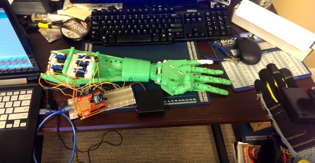
Here's a video of the hand and the glove working together. It's the same video as shown at the top.
As you can see in the video, the servos wouldn't move to its maximum position. Maybe there could be something in the program that I can adjust to make the servos rotate all the way. I tried adding some numbers in the setAngle equation but it seemed that it didn't make much of a difference.
If anyone wants to help me out in figuring this or have any recommendations, please do by writing a comment in the blog. I'm still learning so anything will help me. Another issue that I was having was that sometimes the fingers don't move well and smoothly. I think that source of this problem would probably be individual parts of each finger. Maybe some of them don't interface with each other perfectly.
If you have any questions or would like to know anything about the setup, just drop a comment and I'll try to get back to you as soon as possible.
Simply using a hand from an opensource robot called Inmoov and controlling it through the use of a glove and XBees. The full size robot of the hand can be found at InMoov.fr
- Actuators / output devices: Servos
- Control method: ZigBee (XBee) wireless