


Mechanic:
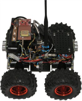
Wild Thumper 4wd chassis
Motors upgraded with encoders
Total weight: 3.3kg
Power supply:
Battery: 2x 7.2V NiMh, fused with 30A (slow)
5V via voltage regulator D24V50F5 (5A), fused with 3A (fast)
The two batteries are connected in parallel using a LM5050-2 active ORing circuit each. Another LM5050-2 can be connected in parallel for docking station supply.
Computer:
Solid Run Hummingboard (i.MX6 ARM Cortex-A9 Quad Core 1GHz, 2GB RAM)
AVR Atmega32 for motor control
AVR Atmega328 (Arduino Nano) for I/O
Peripheral:
Hummingboard: GPS (uart), IMU (USB), 3D-Camera (USB), 2xAVR over I2C, PCA9517 "Level translating I2C-bus repeater" to bridge the 3.3V with the 5V I2C.
Motor control:
Motors driven by 4x VNH2SP30, one for each on a 20kHz PWM
Speed control (PID) and Odometry from wheel encoders are calculated on Atmega328 (yes, doing float on it).
Inputs/Outputs on Atmega328:
3x distance sonar sensors, 2x infrared distance sensors, battery voltage
Odometry calculation:
Odometry from wheels corrected with Tinkerforge IMU Brick 2.0 with Kalman filtering
Sensors:
Xtion Pro Live depth camera
2x IR 2D120X (1x left, 1x right)
3x sonar SRF05 (2x front, 1x aft).
The point of the sonar sensors is to correct the dead zone of the depth camera in less then 0.5m
Software:
Debian Stretch
Robot Operating System (ROS) Kinectic
Full details on the hackaday.io project page.
With two ultra-wideband (UWB) modules, one on each side, the robot can follow a third UWB module. In the following video attached to a remote controlled car:
More details in the hackaday.io project log.
Driving a square from four GPS waypoints. In the following video the front camera is shown on the lower left, the rviz map video is shown on the upper left.
Something useful for my robot to do: Having troubles with the Wi-Fi at my parents house I decided to create a heatmap of the W-Lan signal strength with the inspiration of this ROSCon 2018 talk. Since I did not understand QGIS in a few minutes and because my use case was rather limited I created the map based on OpenLayers instead. An example can be seen in the following image created for my small place:
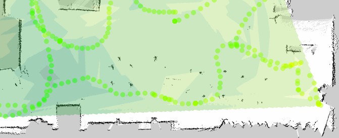 Given an already created floor plan with SLAM I drove my robot around and took a measurement of the Wi-Fi signal strength every 0.5 second. The signal strength ranges from green (very good) to red (very poor). Since I do not have any problems with my Wi-Fi all dots are more or less green for my place. From these discrete measurements a contour plot is generated. In this contour plot it can be easily seen that the access point is in the lower left corner (darkest green).
More details in the hackaday.io project log.
One of the things I want my robot to do is to bring me beer when I'm retired and sitting on the couch. This involves the following actions:
- Drive to the fridge
- Open the fridge
- Locate a bottle of beer
- Fetch the bottle
- Close the fridge
- Drive to me
- Hand me the bottle
My Wild Thumper robot can already drive autonomously to any location in the apartment. To grab anything it does need a manipulator arm, so I have attached a 4 degrees of freedom (DOF) Open Manipulator with a RealSense D435 depth camera:
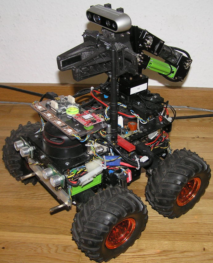
The manipulator can be extended to 6 or more DOF if necessary. Communication with the Dynamixel servos is done with the AVR half-duplex software UART library by Ralph Doncaster on an Attiny85 that translates the commands from the I2C bus. The inverse kinematic of the Open Manipulator is calculated with IKFast and is controlled with MoveIt:
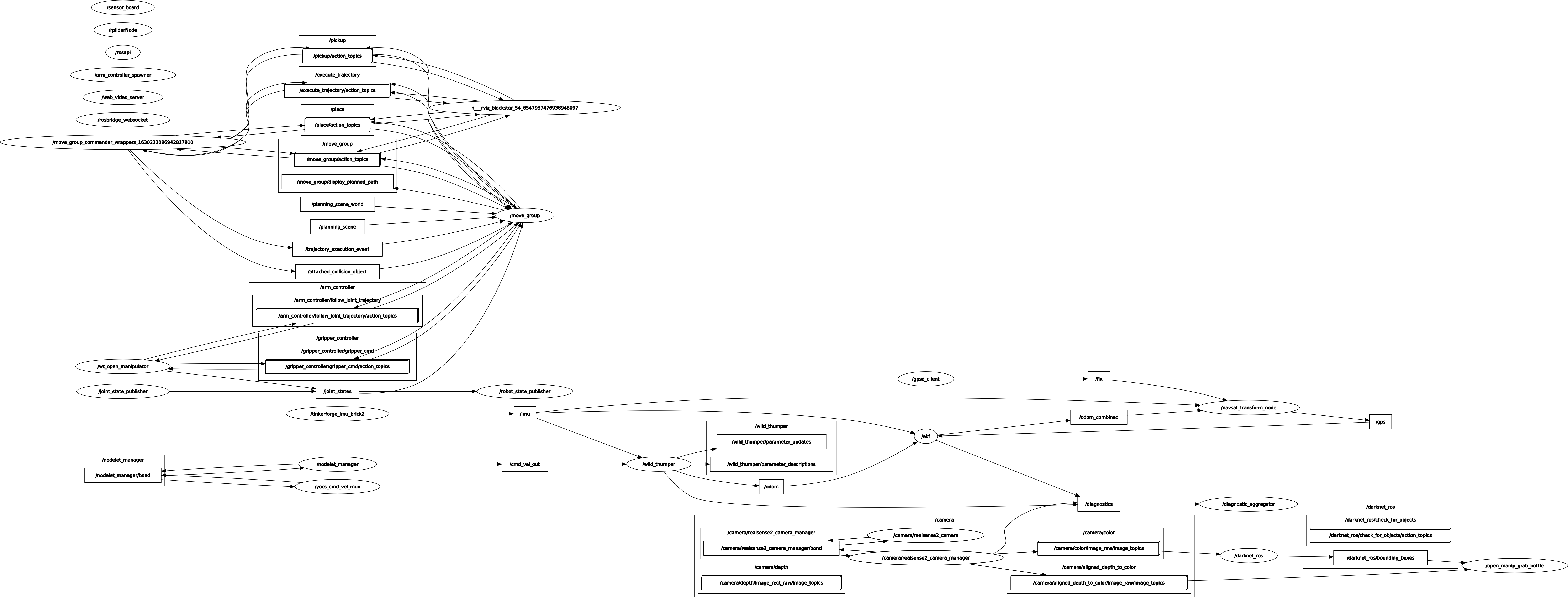
So now I can position the manipulator to any given x/y/z-position that is physically accessible. The next task is to detect, locate and grab a bottle. The detection is done with a YOLO Real-Time Object Detection neural network, the 3d location is then determined from the distance given by the 3d camera and the grabbing is done with MoveIt. For this the following ROS configuration is used:
The realization with the Realsense 3d-camera is done in the following steps:
- Use a neural network (NN) to detect a bottle in the RGB-image of the 3d camera. The NN runs on a stationary computer because the robot does not have a NN accelerator. The result is a box with row, column, width and height.
- Calculate the middle pixel coordinate and get its distance from the depth image. For this the depth image needs to be aligned to the RGB-image. The Realsense node can do that automatically.
- With the known orientation of the 3d camera use projectPixelTo3dRay() to transform these values in goal coordinates x/y/z, relative to the robot.
- Position the gripper of the manipulator 5cm before the goal
- Open the gripper
- Position the middle of the gripper on the goal
- Close the gripper
- Move the manipulator to a final position.
The resulting MoveIt script is in the Git repository and the video shows what it looks like: