


War Pig - Line Follower Robot
Hello,
I'm proud to show you my first robot.
Its name is "War Pig" and it's a line follower.
I'll give you some technical specifications about the project.
Let's start from the electronic schematic.
The core of the circuit is the PIC18F4331. I know it's definitely over sized for the project, but since it came as a free sample, I didn't loose time to find a cheaper one.
Ground color is detected through two photoresistor. The signal is read in the middle of the serie between a 2-20k photoresistor and a 10k resistor: with this configuration the difference of voltage read from the adc is quite high, and can be easily treated like a digital input.
Motors are actioned by the L293D driver. PWM signals move the enable pins and set the velocity of the wheels through a simple algorithm.
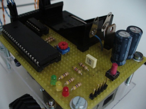
Power supply is made with a 9V battery regulated by a standard 7805 voltage regulator. This is the worst part of the project, since I used the same power supply for the microcontroller and the project. I had some difficulties in avoiding the PIC to restart every time a motor was actioned and I finally did it putting a lot of decoupling capacitors near to the microcontroller.
I put the ICSP connector in the back in order to be able to program the robot without removing the PIC from the socket. Very useful idea.
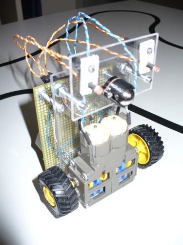
White LEDS allow the robot to "see" the line in a dark room.
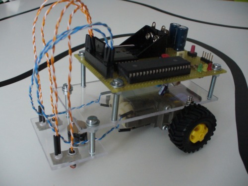
Structure is made with Plexiglas and long screws. It's light and simple but it took me a long time to make the several holes in it.
Here are some pictures:
Bill of Materials:
PIC18F4331 Microcontroller – FREESAMPLE
Resistors & Capacitors – €5 (approx.)
Sockets, Connectors & Wires - €3 (approx.)
2 * White Led - €0.80 ea.
2* 2-20k Photoresistors - €0.80 ea.
L293D - €2.5
MC7805 – 1€
9V rechargable battery - €4
2 * Wheels - €3 both
2 * DC Motors - €14 both
Ballcaster - €3.5
Plexiglas - €2.50
Screws - €0.50
Bill of Time:
Construction – 6 hours
Soldering – 6 hours
Programming – 4 hours
Prototyping the circuit on the breadboard – 10 hours
Personal comments:
+ it works
+ it's cheap
+ photodetectors work well even if not well shielded
- bad battery last
- bad power management
- dc motors are not very precise
- quite slow
Please, please post your comments here or on youtube and feel free to ask for any further information about the robot.
Line follower
- Actuators / output devices: DC Motors
- Control method: autonomous
- CPU: PIC18F4331
- Power source: 9v battery
- Programming language: C
- Sensors / input devices: Photoresistors
- Target environment: White ground