


Wall-e MkII
So, the Rebuild begins...
My first foray into robots, arduinos and electronics in general was a conversion of a Wall-e Push toy conversion ( https://www.robotshop.com/letsmakerobots/wall-e-push-toy-conversion ). It was a great learning curve; using the Arduino Uno, its motorshield and a bluetooth module I was able to control motors and trigger sounds from the toy's original PCB. It also led me to rekindling an attempt to learn python to make a small pc-based app to control him too. I did also intend to add motor or servo control for arms and a head, however due to lack of space and power I had to abort those plans.
After a few weeks of action one of the motors within Wall-e inexplicably ceased function. I brought him back to work work to have a bit of repair work carried out. At this point, i remembered i had a second, backup push toy (in case thongs didn't turn out nicely with the first attempt). This was when plans for Wall-e MkII were started, with the intention of improving the MkI build to incorporate those features i failed to add.
Now I am approaching a quieter time at work I will now have my lunchbreak tinkering time back, so work can begin!
Motors
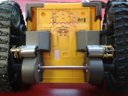
MkI used some lovely little geared motors housed inside the body, connected to the drive wheel using some Meccano sprockets. The geared motors were a late, great, find, and made the meccano gearing a bit unnecessary. It also lead to a very very slow Wall-e!
For MkII I have purchased the same style geared motors, albeit it 100rpm@12v instead of the 60rpm@12v the MkI had - with any luck they may fit in the wheel well without too much hackery (the shaft will be cut off, of course).
Servos
For Arm and Head movement i have got some cheap TowerPro MG995s. The problem here is going to be fitting them; it's going to be tighter than.. well, something incredibly tight!
I have also got an SG90 microservo to possibly use for turning the head if 3 x MG995s wont fit in, however I have doubts over it's ability to turn the head. More to follow in future updates!
Power
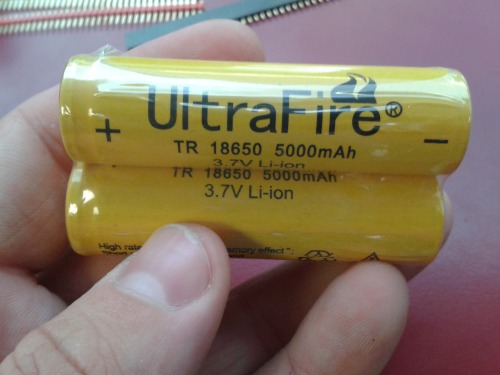
To power the MkII I have four Ultrafire 3.7v, 5000mAh Li-ion batteries.
The movement of the motors from inside the case will free up some precious room to add these. combined with a charging circuit these will greatly improve on the 2 x paralleled 9vs I have in MkI!
I was going to be using a 12v regulator to drop the voltage for the motors, however thanks to Birdmun and 6677 et al in the Shoutbox i will be using PWM to run the motors at 83% power; close enough to their ideal.
A 5V regulator will facilitate power for both the servos and also the controller board.
Controller Board
This area has undergone many, many revisions while I've been thinking about it.
The MkI Uno/motorshield combo (combined with its library) was brilliant for a beginner such as myself. However, with me only requiring 2 motors it wasn't very pin-efficient.
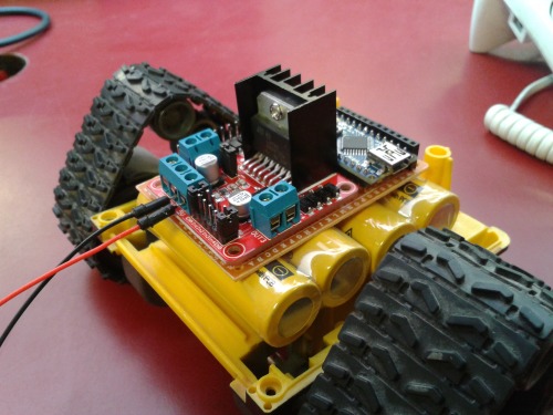
I at first toyed with the idea of replacing it with a Nano and a L298N breakout board, then introduced an idea of a Nano breakout board to simplify the connections.
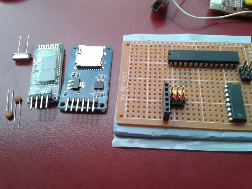
At this point i decided to just use the cips directly - i currently have an L293D for motor driving, and an ATMega328P to replace the Nano. Work is underway now trying to create the breakout board. Hopefully it will be small enough to fit in the currently-redundant battery compartment on the back of Wall-e.
Pin Mapping - updated 02/07/2014
As i am currently still working through my board I haven't working out what pins will be dedicated to what.
I will update this section as i go, but the current board requirements are:
Board connections
6 Pin - SD Card (Female: CS - D2, SCK - D13, MOSI - D11, MISO - D12, VCC, GND)
4 Pin - Bluetooth (Female:Tx -A0, Rx - A1, 5v, GND)
3 Pin - Servo1, Servo2, Servo3 (Male: Data - A3,A4,A5, 5v, GND)(sharing 5v and GND rails)
2 Pin - Eyes (Female: LEDPin - A2 GND), Speaker ( To be connected via transistor )
L293D Pins
D0
D1
D2 - SD Card CS
D3 - Bluetooth Tx
D4 - Bluetooth Rx
D5 - For L293D (PWM)
D6 - For L293D (PWM)
D7 - For L293D
D8 - For L293D
D9 - For L293D
D10 - For L293D
D11 - SD Card MOSI (also for SCPI header)
D12 - SD Card MISO (Also for SCPI header)
D11 - SD Card SCK (also for SCPI header)
A0 - Speaker
A1 -
A2 - Eyes
A3 - Servo1
A4 - Servo2
A5 - Servo3