


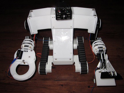
Very Advanced Droid Exploration Robot (VADER)
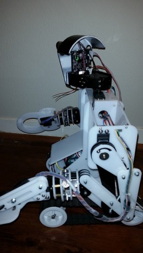
This is my Service Droid. Meet VADER, the Very Advanced Droid Exploration Robot. Ok, I admit it, the name is a stretch but it was fun to come up with. Everyone knows that Darth Vader was OB1's apprentice until he turned to evil. :)
I'm going to attempt to chronicle the final assembly of the Dagu Kit, designed by OddBot and also the additions and modifications I hope to make to it. I'm planning to use a Spider Controller and a 4-Channel Controller, both also produced by Dagu.
Here are my hopes for this little guy:
1) To start off with I want to make him radio controlled so that I can get used to how he moves and what he an pick up and put down.
2) I want to outfit him with some environmental sensors and a wireless camera so that he can gather and transmit information about his environment. I have a Wixel I've been dying to use on a project.
3) My ultimate goal is to be able to set him down in a closed environmnet (ie 4 walls) and have him autonomously find and retrieve an object and return it to is starting point.
A few starting Concerns:
1) I may add another controller (I have a couple Arduino Megas on hand as well as some Picaxes) if I can figure out how because I'm little concerned that I could run out of IO pins. I'll be chewing on this while I assemble the kit.
2) This is only my second Arduino project so I'm going be slow at developing my own code. Fortunately OddBot has done a lot of work that I'll scavage from to get me going.
3) I have limited time to work on this hobby so this could be a very long and drawn out process.
With those lofty goals and few concerns in mind, let's see how this puppy turns out....
Part 1: Preparing the Parts
Before assembling the service droid you have to remove the various acyrilic pieces from their frames. Take your time with this as it's possible to break a part if you get rough. You can remove the parts as you need them per the assembly instructions, but I decided to remove all of the pieces and rebagged the in ziplock bags. After working through a couple frame with a pair of dikes I switched to a flush side cutter new bought off Amazon frabout $7USD. I sanded down any remaining evidence of the tabs with a nail file. I did manage to break one piece and reglued it with Super Glue (see the picture).
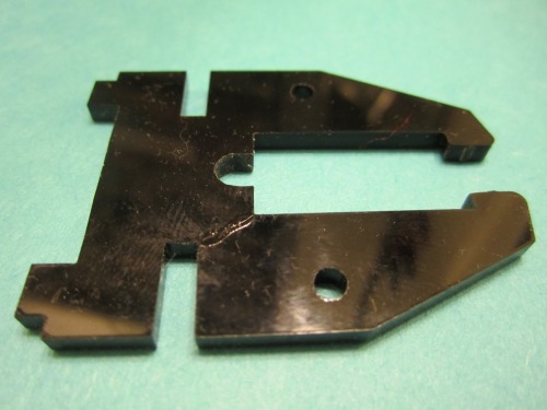
Figure 1. - Broken Piece Glued Back Together
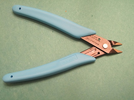
Figure 2. - Flush Side Cutters
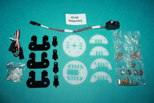
Figure 3. - Pieces for one of the Wrists
Part 2: Modifying the Servos
I also started modifying all of the Servos at this point. I did this pretty much as the directions said except instead of putting hot glue to hold the servo body together I used mini-clamps. I don't have OddBot's skill with hot glue and didn't want to risk the mess.
The only issue I encountered in making the modification was accidentally desoldering the existing wire from the pot inside the servo. I didn't have much difficulty in resoldering it in addition to adding the new wire but it made me nervous the first time. I thought I might have ruined the servo.
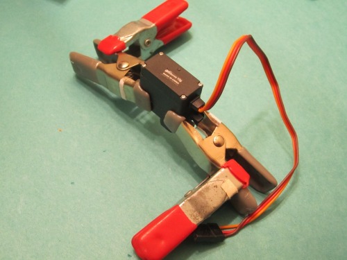
Figure 4. Mini Clamps to hold the servo together and keep it upright while adding the sensor wire
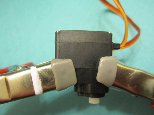
Figure 5. - Closeup of Clamped Servo
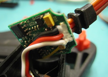
Figure 6. - Inside of large servos (shoulders and pan/tilt assembly)
The insides of the large servos are different than the small servos that OddBot used in the servo modification directions. After talking to OddBot about this configuration he recommend soldering the added wire directly to where the pot wire is soldered to the circuit board. When you open up the servo though you'll see the solder joints are covered in a white potting/staking compound. The wire from the pot is the midddle (red) one. You'll need to carefully scrape the compound off the middle solder joint. Figure 7 shows the exposed solder joint.
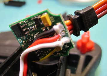
Figure 7. The white potting compound scraped away from the middle solder joint.
After making the modification to the servo I tested it using a Servo Tester and a Multimeter. The Servo Tester has a manual control where I can move the servo to any position by turning the knob on the tester. When I took each servo to hardstop in each direction the voltage on the new sensor wire varied from about 0.86V (0.89V on some) to 1.75V. In the Neutral position, as found by the Servo Tester, it measured 1.34V. This was approximately the same result on every servo. I claimed success on the servo mods and moved on.
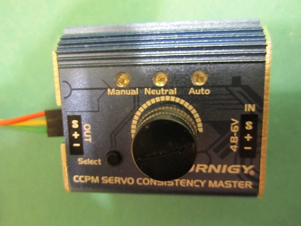
Figure 8. - Servo Tester
Part 3: Kit Assembly
After removing all of the pieces from their frames and sanding off the little tab stubs I'm ready to start assembling the Service Droid per the onlne instructions. Here are some pictures I took as assmembled. I tried to take special note on any steps that I thought my trip someone up.
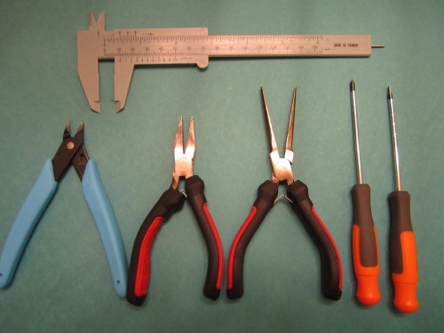
Figure 9. - Tools I used in the Assembly
I started the assembly of the two wrists as orderd in the manual. I let the wrist servo wire extend out as shown below. Not sure if that was right, it's possible it could extend out below the lower white semicircles.
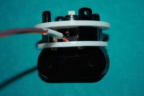
Figure 10. Beginning of Wrist Assembly Showing Wire Routing.
When installing the wrist bearings it wasn't immediately clear that the small cylindrical spacers where supposed to slide inside of the bushing. It took some force when screwing on the nut to get it into place. I used a pair of flat pliers (on the locknut) and a screw driver (on the screw) to tighten it together.
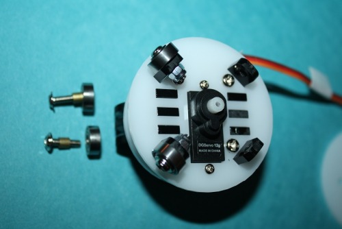
Figure 11. Wrist Bearing Installation
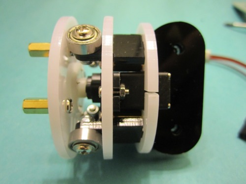
Figure 12. Completed Wrist
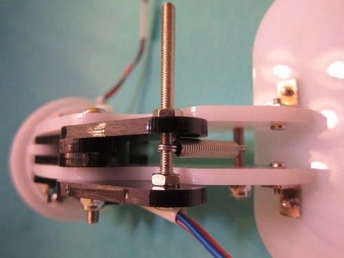
Figure 13. Closeup of Lower Scoop Assembly with Spring.
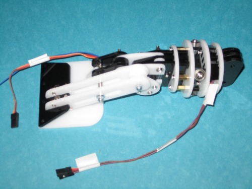
Figure 14. Completed Scoop and wrist
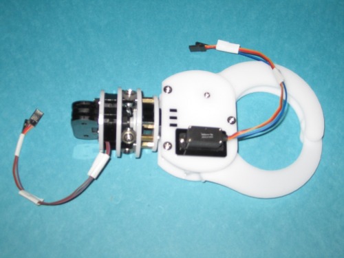
Figure 15. Grasp Hand and Wrist
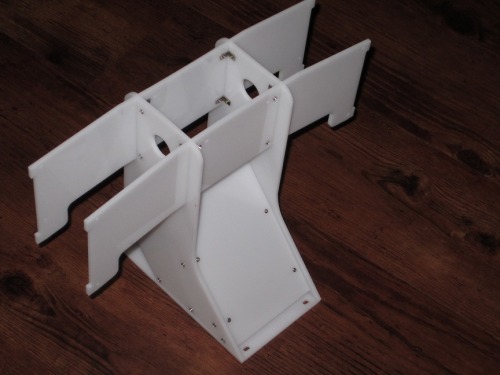
Figure 16. Completed Torso
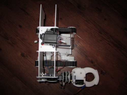
Figure 17. - One Armed Bot!

Figure 18. - Completed Kit
Part 4: Wiring up for Remote Control (Future)
Next step is to wire up the Rover 5 to the Dagu 4 Channel Controller. I plan to use 8 Tangsfire NiMH AA 3000 maH batteries as the power supply here with the same trickle charge circuit that OddBot used on OB1. The 4 channel controller will be wired to a Dagu Spider Controller. The Spider will be Vader's central brain with the Service Droid servos connected to it. To test Vader's arms and mobility I want to control him using a HobbyKing 6 channel Radio Controller and Receiver (one of those $25 jobbies I got a while ago).
Update: Jan 8, 2014
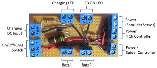
Figure 19.- Power Distribution/Charging Board
Threw together a small board based on the battery charging curcuit that I ripped off of OB1. Not pretty, but it works.This board will sit just inside the opening of the SD and Rover 5 base, It provides separate power connections for the Spider Controller, 4 channel motor controller, and shoulder servos.When/if needed, the power for the shoulder servos will be further reduced downstream. The back end of the Rover 5 base will have the on/off/charging switch, two LEDs (charging and on), and a jack for the plugging in the AC/DC adapter for charging.
Update Feb 17, 2014
I've wired up the 4 Channel Controller and Spider to the Rover 5. I hit a few small challenges along the way but's together.
The first problem I had was that the wires in the Rover 5 that I needed to connect to the 4 Channel Controller were too short for my config. I thing the culprit was the power board I added. The power board sits below the Controller so the Controller had to sit up on standoffs. I had to generate some extensions.
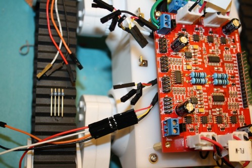
Figure 20. Adding Wire Extensions to the Rover 5 Wires
The next issue I came across was the type and quantity of jumpers that I needed. The 4 Channel Controller has male pins and I'm connecting them to female pins on the Spider. Luckily I had enough of those types, but just barely. Since I was tying together PWM and direction pins on the left side motors and again on the right side motors I had to get creating with creating some Y-jumpers that would fit. It involve cutting my few remaining female-female jumpers and splicing them onto an extension.
I should note that I found it helpful to remove the base off the Service Droid assembly and mount it separately. By doing this I could install the 4 channel Controller and Spider without having the Droid Torso in the way.
I also modified one of the adjustable voltage regulators to add a +/- headers and screw-down terminals for supply power. This particular regulator a adjusted to provide 7V for the shoulder servos. I'll eventually add 9V regulator and 5V regulators to power other equimpent and sensors.
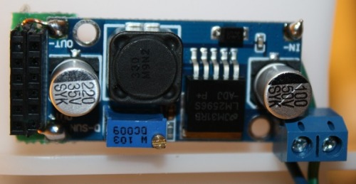
Figure 21. - 7V Regulators with added headers
I finally got the Spider mounted and connected to the 4 Channel Controller and the Service Droid body put back in place. Next step will be to connect up the Service Droid servos.
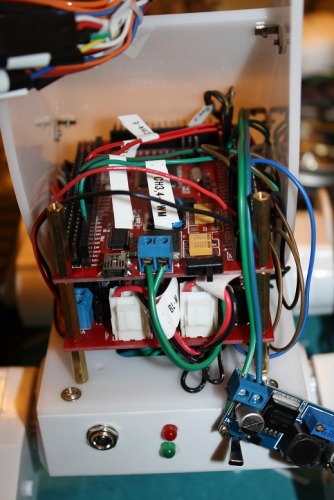
Figture 22. - Spider and 4 channel Controller installed.
Part 5: Display Backpack
I have a 128x64 display to attach and wire up, ala OB1. Given that I've modified all of the servos in the Droid body I hope to be able to relay the position of the arms and pan/tilt assembly in some graphical fashion on the display, along with the data from the forthcoming sensors.
Part 6: The Head
From the first moment I saw the SD kit i had an idea for the head. The tentative plan is for it to include 2 SR04 ultrasonic rangefinders, a minature wireless camera I have on hand, and a speaker with Arduino supported MP3 player. The MP3 player is model WTV020-SD. The MP3 player should arrive by the end of January.
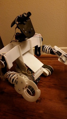
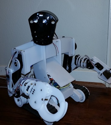
Short Update (10/5/15)
Some time ago I began building VADER's head, but haven't finished it. Thought I would atleast post what I did. The head is a PVC endcap that I cut on a band saw then spray painted black. It works OK, but now that I have a 3D printer I'd like to design and print one that will do better. I've mounted the Pixy Camera and the early version of LIDAR Lite, but haven't programed the bot to use them yet. Remaining holes are for a small speaker at his mouth and some LED lights and a laser pointer. The head articulates up/down and left/right to look around this surroundings.
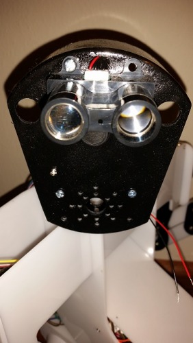
I wanted to use the Pixy with the LIDAR Lite to identify and option, then autonomously navigate to the object, retrieve the object and the return to his approximate original location. More to come!
Part 7: More Sensors and Wireless Communication
I have a 9-DOF IMU with Digital Compass I've been waiting to use on the right project and this is it. Additionally I want to add temperature, pressure and sound sensors. All of this I want to not only display on the backpack display, but also telemeter back to a computer using a set of Wixels that I've already bought.
A couple functions:1) Remote Control 2) Autonomous avoidance 3) Autonomous object retrieval (hopefully)
- Control method: autonomous, radio control, Bluetooth
- CPU: Spider controller
- Operating system: Arduino
- Sensors / input devices: video, Sound, ultrasound, temperature, humidity, IMU
- Target environment: indoors