


UPDATED Acrylic Arm
Hey look, a new description! \/
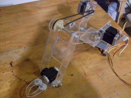
I started this robot over a year ago. I happened to have just recieved a box of parts from a copy machine and was astounded by all the goodies. What stood out to me the most were those 2 wonderful steppers down below. My first thought was "CNC machine ya!", but I decided I didn't need ones that big for a desktop CNC machine. A few days later I thought about having a robotic arm mounted on my desk. So I went and looked through my copy machine parts box and found that bracket\motor assembly. As I marveled at the beautifully large gear I realized this would make a great base. The large gear would give a slow enough speed and high torque. Then after looking up the datsheets for those two motors I realized they would be great shoulder and elbow motors.
The next day I made a very rough list of parts and went to Lowes. I bought some random bolts, nuts, washers & a sheet of acrylic. After I got home I made a couple paper templates and traced them on to the acrylic. I am not the kind of person who makes a plan for my robots. I just kind of ad-lib it. Anywhositnow, the next day I cut all the pieces, drilled them, and epoxyed them. Then the day after that when the epoxy dried I mounted the motors and left it...for...a year. Yes I know, who abandons a robot when it is so close to life. It actually was almost complete except for a wrist and gripper.
About a week ago I came across this website and decided to post my robots. That is when I noticed my robotic arm sitting sadly on the back of my desk. Thanks to this website, the arm now has a wrist and gripper! I had asked in the comments below for some gripper ideas and I came up with this: servo wrist, claws synchronized by gears, Flexinol (an SMA wire like Muscle wire) actuated gripper. Dowm at the bottom you can see the gripper design.
Now I am working on the controls. I have planned to control it by a custom made Visual Basic program, but I know very little about interfacing a program to a parallel port. YES I WANT TO USE THE PARALLEL PORT. I like the simplicity of a parallel port. So if you could suggest how to use the parallel port in Visual Basic, I would mucha appreciate it. Enjoy.
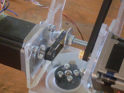
I couldn't have made the belt on the shoulder motor any tighter. I have tried to make the belt slip and was very pleased to find I couldn't.
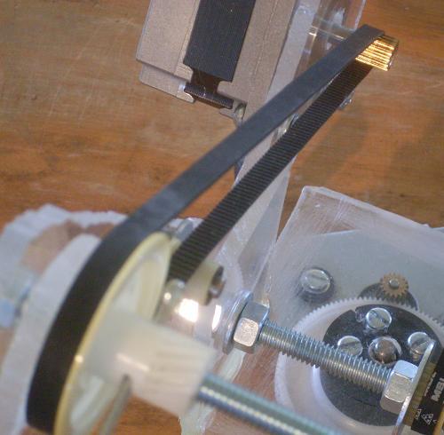
The picture above shows the elbow joint and the belt that runs from it to the elbow motor at the shoulder. You can't really see it, but near the elbow is a tensioning wheel.
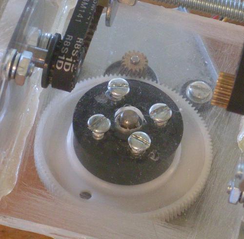
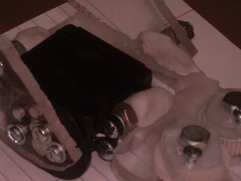
above is the rotation motor. The gears on the shoulder and elbow motors just happened to fit the belts perfect.
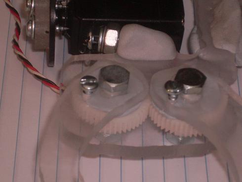
This is the gripper I made. The two fingers are epoxyed to the gears and they will be actuated by Flexinol. The screw on the left is for a spring to return the gripper to the open position.
This is the servo on the wrist. You can tell I like epxy putty. The epoxy putty was placed on the gripper base and the screws inserted while it cured. This ensured a perfect thread when I attached the servo. The sevo is attached onto one side of the arm by a large serbvo wheel. The other side has a bolt epoxyed to the gripper base.
Robot arm things
- Actuators / output devices: large stepper motors
- Control method: semi-controlled through a computer
- CPU: none yet
- Operating system: none
- Power source: 24 volt PSU
- Programming language: Visual Basic
- Sensors / input devices: ultrasonic, will have pressure, potentiometers
- Target environment: indoor, my desk