


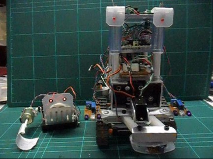
Umbot & the Magnetnator
This is what my 'half a robot' blog turned into.
For some construction Photos see here: https://www.robotshop.com/letsmakerobots/node/23442
Magnetnator Features:
- 1 - 20M picaxe
- 2 - 08M picaxe - one to run the PWM on the motors as the 20M has no PWM pin & the other runs the magnetometer
- IR sensors
- 1 - 433 MHz transmitter
- 1 micro servo
- 2 battery packs
- Lots of Blu Tack
Umbot Features:
- 1 - 08M
- 1 - 433 MHz reciever
- 1 - micro servo
- 1 piezo speaker
- More Blu Tack
WHAT DOES IT DO?
The Magnetnator rolls around looking for magnets and tells Umbot when he finds one.
Umbot chirps (don't know if you can hear it in the film)
and then waves the flag when he gets a signal.
SOME INTERESTING THINGS I LEARNED
- Both sets of eyes are powered by the serial communcation signals between the chips and
this is a good way of getting extra features for no extra pins or programming.
It also lets you see that something is going on, especially when the motors are off to save power.
Only the LEDs connected between 2 picaxe boards had enough current to run.
I had to use a transistor to power Umbots eyes from the 433MHz reciever. It was weak.
- Very important thing I learned.
If the robot starts behaving differently CHECK YOUR BATTERIES!
I spent about 3 hours adjusting settings when all it was was low on power. Duh!
- Another very important thing I learned.
If it won't do what you want it to and your code looks right... it's not!
keep looking you've made a mistake somewhere. ;-D
- Oscilloscopes are invaluable to work out how to link signals together.
The easiest way to get the 'back away and turn' routine to trigger from the magnetometer board with it's seperate power supply
was to join the grounds and link the 'serial out' transmission signal to to the adc pin of the right front IR sensor with a 1 Meg
Ohm resister. As seen in the video above when detecting the IR light the voltage drops, but the serial makes it spike so I can
get the same response from 2 different sensors. The scope helped me work out what was going on.
SOME PHOTOS
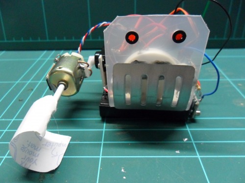
Umbot.
I soldered copper wire onto the motor and tied it to the servo horn.
Worked really well, nice and steady.
Spot the BluTack.
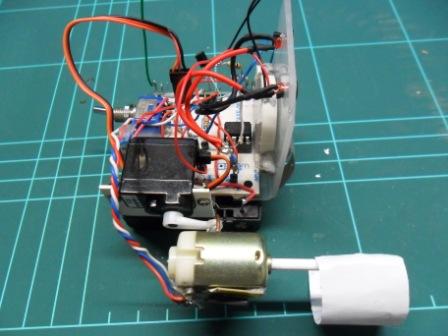
Before the magnetometer was added.
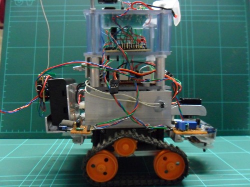
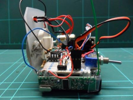
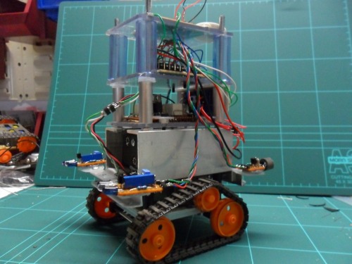
The Magnetnator complete.
SUMMARY:
- Over complicated but fun project. If I were to push it any further things would start malfunctioning / breaking.
- Now i've used up left over MCUs it's time to get a more serious board to work from, at least a 28X1.
- Would like to build a 'super' magnet sensing circuit as some people have been talking about.
- Also if I could program the hall circuit to be self calibrating i'd be very happy. I boosted the UGN350UA's output with a darlington transistor but it drifted something shocking and I had to keep changing the ADC parameters several times a night.
All attempts to read the input at startup and set deviation from that reading nearly ended in tears. Don't know why but it was always different to the in scan readings. ??? :-(
Drives around & detects magnets
- Actuators / output devices: Tamiya Gearbox, Micro servo's, toy motors, Tamiya track and wheel set
- Control method: autonomous, Easy Radio wireless.
- CPU: 3 Picaxe 08M, 1 Picaxe 20M
- Power source: 5X1.2v AA, and 2 (3X1.5v AA)
- Sensors / input devices: Beefed up Hall Effect sensor, IR obsticle detectors
- Target environment: Indoors is best