


tinyTableBot
UPDATE: attached code
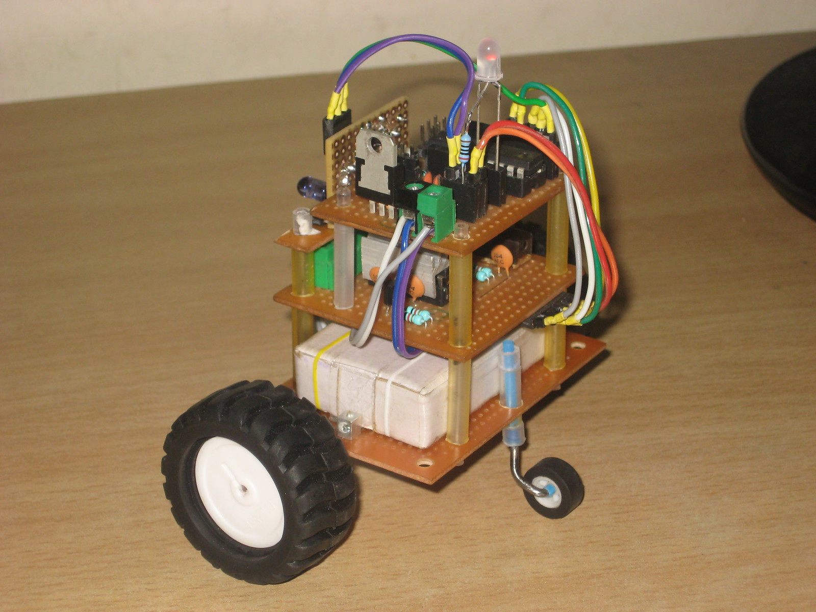
Hi, Meet the tintTableBot. It is called tiny because of 2 reasons- it uses an Attiny2313 and it is small. Although it is an obstacle avoider and can move on most flat surfaces indoor, I still like to call it a table bot as it remains on my work table for most of the time, hence the name tinyTableBot :)
Introduction
About six months ago, I was writing code for my LED matrix project in the arduino IDE. I made my own hardware, so it was something which made me think hard in the coding part as putting up a forum or asking for help from someone meant I had to explain them the complete circuit/schematic first!. It was then that a random thought came to my mind, what if I had to make this using a bare microcontroller (arduino-less)?. Arduino makes everything very simple, there are 'libraries' for most of the sensors, peripherals etc. and all the complexities involved in interfacing them with the microcontroller are hidden behind the clean looking 'functions'. I then developed an urge to learn about the behind the scene actions happening inside these functions (and the microcontroller itself). Although I knew that arduino just sits on top of the AVR microcontrollers even when I started using the arduino and that the actual thing is different from what it looks, I just decided to leave the arduino (for a while) and start learning to program the bare AVRs.
So, after a couple of months of procrastination, i finally bought a Attiny2313v and made myself a experminter/dev board on a protoboard. I chose the attiny2313 for many reasons, it is cheap, it has a nice and easy pinout, it has 2kB internal flash (more than i needed for most of the learning topics), two timers, 4 PWM channels, UART, I2C etc... I started with the basics like blinking LEDs, controlling motors etc. and later moved onto some advanced topics like using timers, interrupts, interfacing shift registers, ADC (although attiny2313 doesn't have internal ADCs, i moved onto atmega16 to try this very useful feature), communicating over UART etc. After implementing these features in small experiments and getting somewhat familiar with the AVR environment, I wanted to make something which incorporates these features in a single bigger project. So, what could have been better than a robot for this purpose? I think this is the best way to learn about something, when you combine all the small topics together into a bigger thing. This is how tinyTableBot was born. :)
Construction
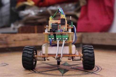
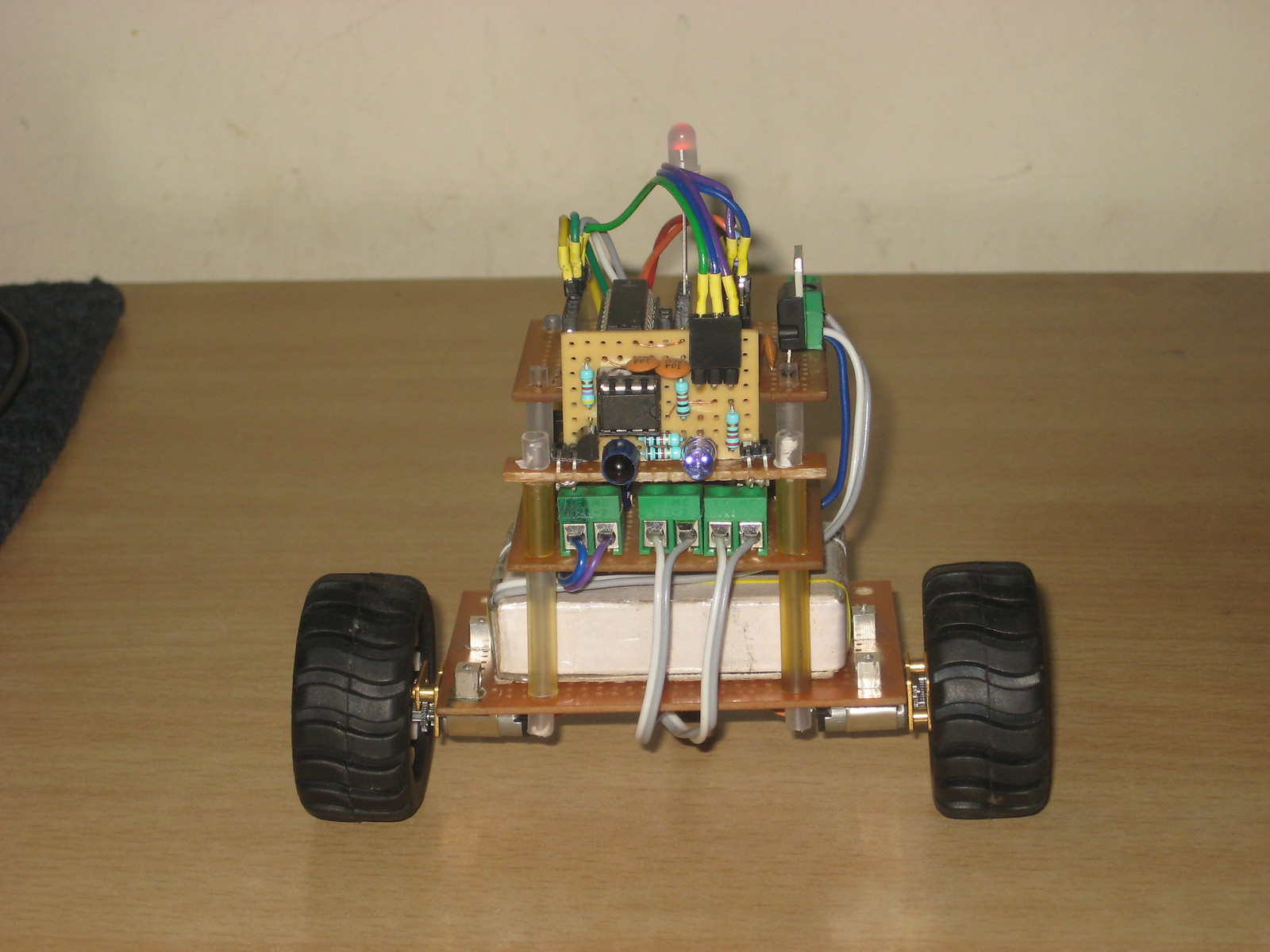
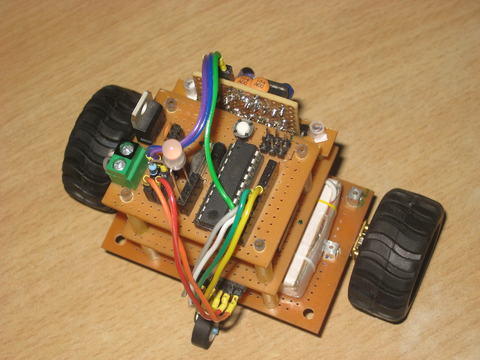
The construction is fairly simple, it is made of 3 'layers'. As you can see in the images below, I structured most of the bot with protoboard pieces. The motors are attached to the bottommost board/layer, the middle layer is the motor driver board and finally the top layer is my attiny2313 dev board. On the front is my PWM based IR distance sensor (more on that later in the post) that detects any objects in front of the bot. I basically took whatever was at hand and chose the best fit.
(click any photo to enlarge it)
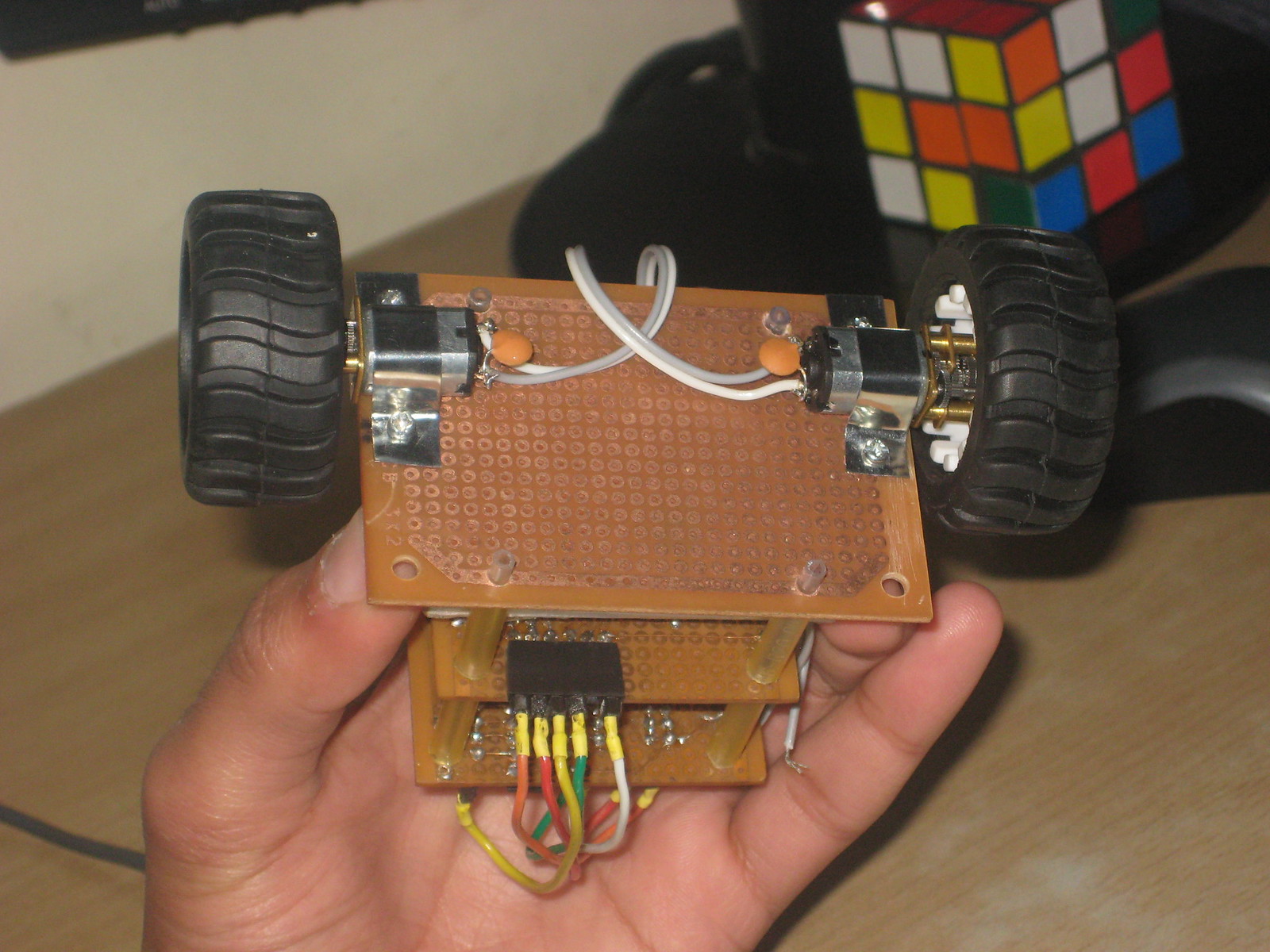
About a month or so ago I ordered two microgear motors (I don't remember the gearbox ratio) from ebay for a two wheel balancer but it turned out that the motors/gearboxes are too slow for a balancer. No worries though, they are still perfect for a indoor/table bot like this :D I couldn't find proper brackets for mounting these motors so I made them from an AA size alkaline battery's metal cover.
(lacking the castor wheel)
I couldn't find metal or plastic spacers in any of the hardware shops in my town, so, I used refills from pens! It may look a very flimsy arrangment but it is actually quite sturdy, you can shake the whole bot holding the top board/layer without any issue/damage etc.. While drilling holes in the boards, i carefully selected the right diameter drill bit so the thinner (ball pen) refills fits tightly and holds the boards in place while the thicker refills are used as spacers between layers.
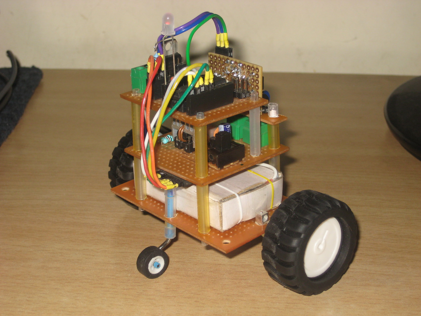
The battery pack sits on the base layer below the motor driver board. It is basically made of two nokia 3.7 volt batteries connected in series. I use a old nokia phone to charge them which means i can't solder wires on their terminals (otherwise they won't fit in the phone!) therefore i made that little battery holder case which has contact terminals for both batteries' terminals, pretty nifty, right? :p It fits snugly between the four refills and the motor bracket nuts . And there is the nice little castor wheel. I got the wheel from an old casette tape and the rubber grip came from a piece of rubber pipe. The castor is attached to the main body again by the thinner/thicker refill arrangement.
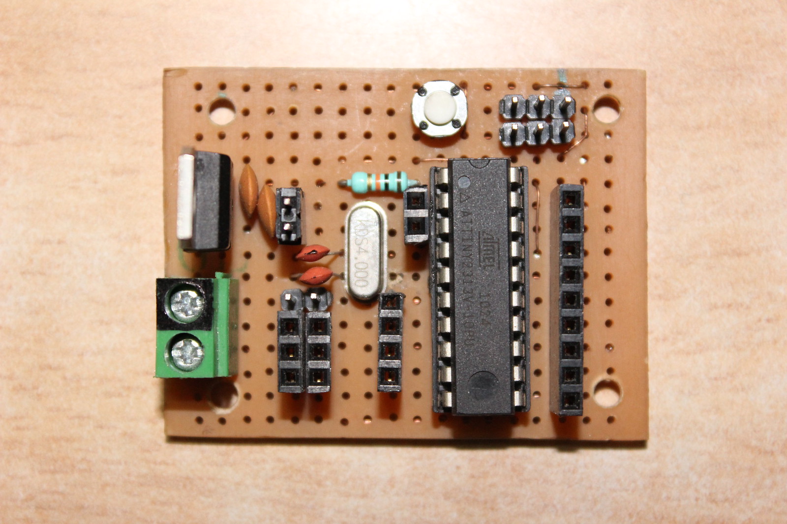
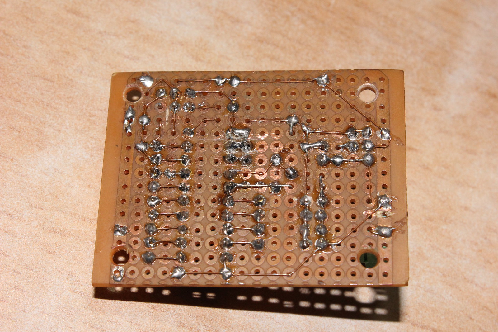
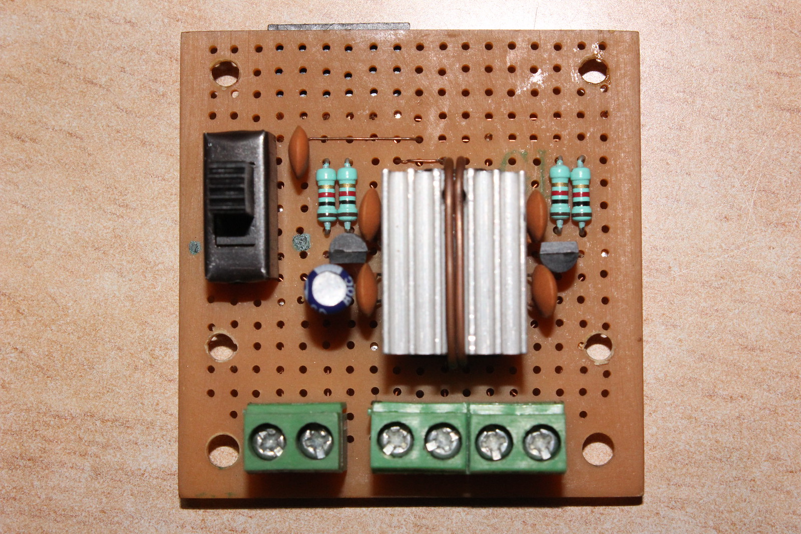
There are three main boards in the bot, my attiny2313 dev, the motor driver and one for IR sensor. Below are the images of the first two. I am using attiny2313 as the uC and L293d as the motor driver. The attiny2313 board has headers for all i/o pins, 5v and gnd rails, 7805 as the voltage reg. (which can be bypassed by a shorting block), a 4MHz crystal for clock and the 6 pin avr isp header for programming. The motor driver board has interface pins on the bottom of the pcb.
(click any photo to enlarge it)
PS. I don't think that heat sink really helps in 'sinking' any heat, kinda looks cool though :p
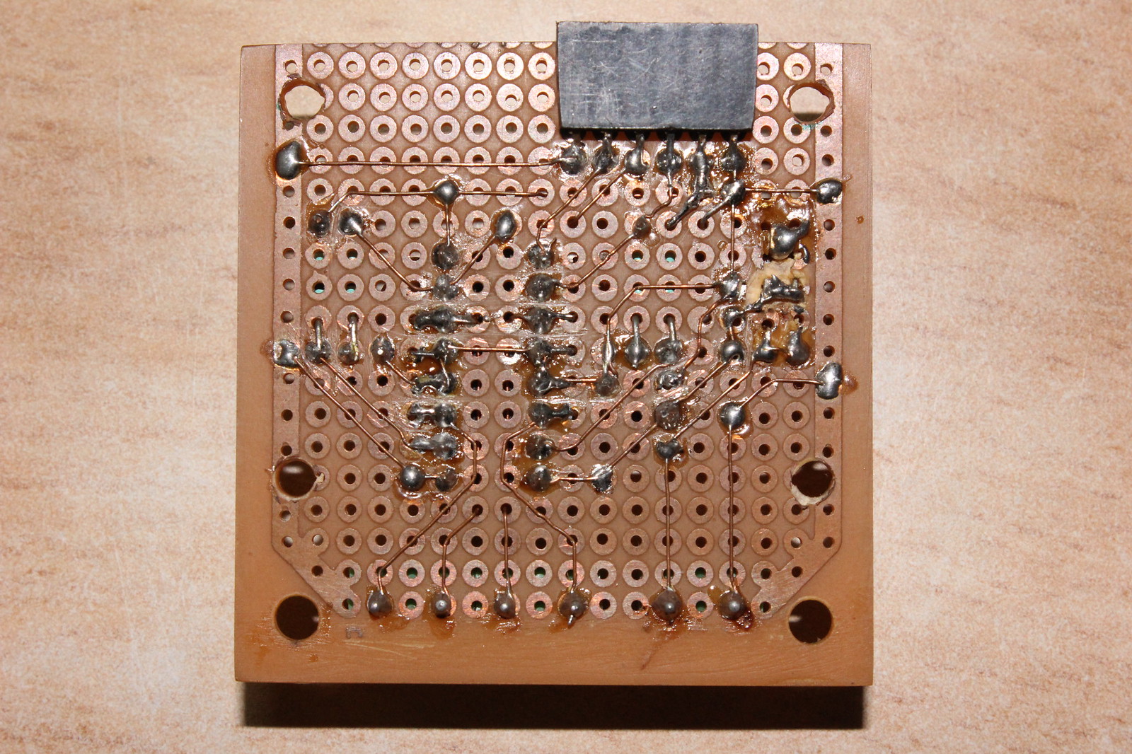
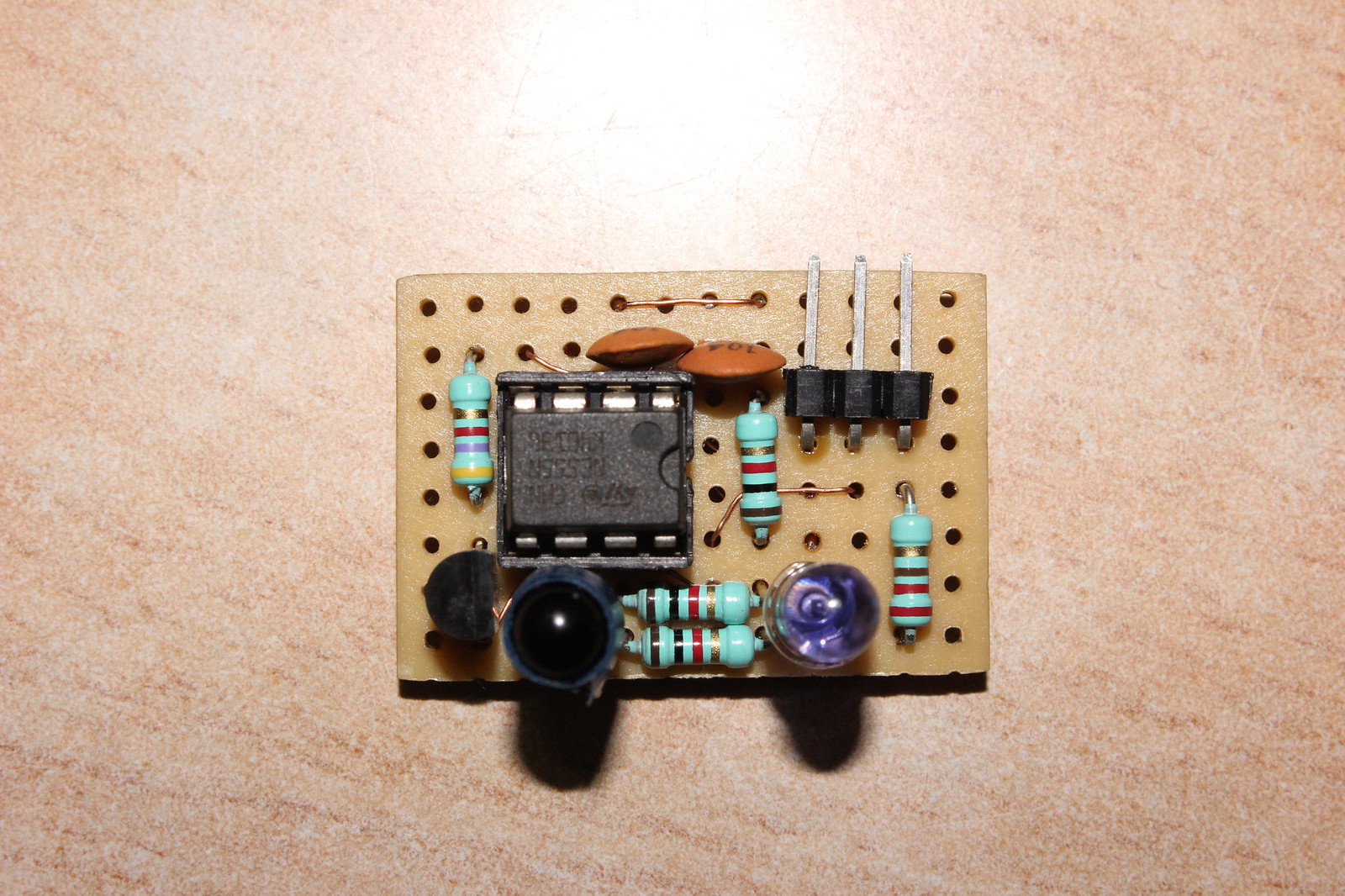
And my PWM IR sensor..Since attiny2313 lacks ADC, I needed some way to make it read the analog distance value. Here is how it works- a bc547 amplifies the voltage from the IR photodiode and feeds it to a 555 timer IC which varies the width of pulses in proportion to the analog voltage. The width of pulses varies from about 200 uS to 420 uS in the working range (3 cms to 25 cms). From my tests, the graph between input analog voltage (fed to the 555) and the width of pulses generated by the 555 timer was not exactly linear but acceptable. But the non linear nature of the IR photodiode (combined with further amplification) made the whole sensor very non linear, at one point the width varies approx 70 uS for a change in distance of 1 cm.

Future?
I am thinking of making a bigger version of this for my Raspberry Pi experiments :)
Thank you,
Sanchit
Helps me learn AVR, Keeps me entertained, Avoids obstacles
- Actuators / output devices: 2 x Micro Gear Motors
- CPU: ATtiny2313
- Operating system: AVR
- Power source: 7.4V Li-Ion rechargeable pack
- Programming language: C (AVR GCC)
- Sensors / input devices: PWM based IR distance sensor
- Target environment: indoors, work table