


Three wheeling doover....
update? - not really, I accidently deleted the youtube link - so I'm fixing it ..
This is not a very intelligent, or special robot - it took me long enough, but it was really just for my education etc.
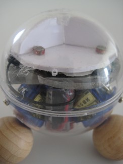
This is about 10cm high, it is a clear ball with three servo motors, driven by three 74AC740 ICs. The ICs measure the amount of light coming through an array of sensors on the top, and rotate the balls in a direction and speed proportionally to that. The result is that the ball "drifts" towards the brightest object, or follows a spotlight directed down at it.
This robot has no other sensors.
what I like most about this guy is that it drifts around - you have no idea which direction it will move, because it doesn't need to "turn" to go in a particular direction.
Some more thoughts to try to make this page more useful...
Learning curve:
The drivers are really only three "headbot" circuits, and I was exploiting the fact that they control the motor according to the differential of light as measured by two LDRs. I already made a two-wheeled robot with the same circuit, and I wasn't too impressed with it. This robot can be "trapped"by putting it in a square of light.
What I learned.
I think that what I learned most is that the hardest part of making a robot is the actual chassis. No suprise to anyone else I'm sure. I also learned that it's ok to completely lobotomize micro servos and use them only as gear boxes - I felt bad doing that initially.
What I'd change.
I think that it's too slow. I think it would be really great to make something that nips around the place by putting higher gears on it - or just skipping the microservos and going for some suitably-high torque motors.
I think it's also possible to put bumper switches on it without increasing the component count too much, and so it can just ping-pong around the place, bouncing off walls like a mad thing.
So here is an attempt to describe how I made it. I'm going to be doing this in installments because I'm busy and important - well, busy anyhow (read "lazy"). I didn't want to take my robot apart too much, and I didn't want to make a brand new one just for this walk thru. I plan to spiff I this idea eventually though, according to the "what I'd change" section above.
Components that I used:
6 x LDRs
3 x 74*C240 (20 pin) ocal inverter chips.
3 x motors (I used some pricy, but cheap quality miniservos - lobotomised to make them just geared mini-motors)
3 x wooden 2cm dia balls
1 ~10cm dia clear acrylic (?) ball shell
1 cannon 3.7V Li-ion battery (it's small, and nice and flat!)
1 switch
various bits of plastic sheet, plastic tube, wire, and the odd bit of hotglue.
Step 1. Preparing the shell & wheels.
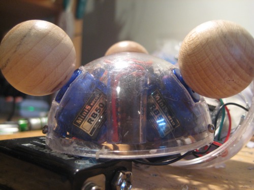
I measured off the most "appropriate" place for the balls to be positioned on the clear ball shell, considering clearance, and trying to get the equator of the balls as close to the ground as possible - to maximise the efficiency of the ball-rotation etc. etc. I think I decided on something that looks about 60 degrees from the equator of the big clear ball.
Cut out mounting holes, and install the three servos and screw them in.
Drill out a small hole in each of the balls for the servo axel, and hot-glue them all in.
The image shows the bottom half of the shell (upside down) , with the motors and balls installed.
Step 2. Preparing the ICs.
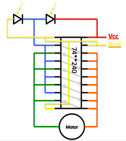
The three ICs are operating completely independently, the only connection between them is ground and power. Below I have a schematic, I haven't put a circuit because not everyone finds them useful. The to LDRs are shown at the top of the schematic.
Before anyone jumps on me, I did NOT design this circuit - it's a common arrangement used in some simple BEAM bots, to control a light-seeking head. Somone else designed it, I don't know who, but I'm sure lots of people will have a claim to it.
The circuit just uses the LDRs as a voltage divider, and switches power from one direction to the other. One set of the four inverters uses the output of the other set to invert themselves. I may post images of my rather butchered ICs later, if people really want to see them.
I should clarify that although I said that this IC rotates the wheels proportionally to the light difference between the two sensors, this is not really true. The motor will be full on in either direction, or off. It's not too tough to make a circuit that DOES do this proportionally; look for Wilf Ritger's Solar-power-smart-head circuit, for example.
In any case, even having non-proportional rotation, the bot can still move in any of six different directions - which is good enough for me, for now
Setp 3. Building the LDR array.
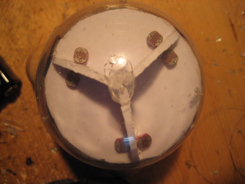 The LDR array is divided into 3 segments, each segment holds the two LDRs for each Motor*IC unit. The two LDRs for a given unit must be separated from each other, but should also be in proximity to the opposite LDR of the adjacent M+IC unit. (i.e. the left-turn controlling LDR for unit 1 must be far from the right-turn controlling LDR for Unit 1, but adjacent to the righ-turning LDR for unit 2).
I put the sensor array in the top half of the shell, leaving room underneath it for the slim battery.
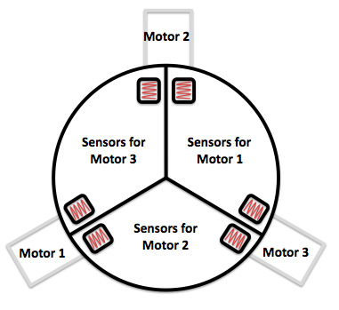
I've made a quick schematic of the robot, looking down from the top, and showing the relative positions of the two LDRs that control their respective motor+IC unit. The relative arrangement of the sensors and the motors is important too. The "section" containing the pair of LDR sensors must be symmetric about the motor. Here is a schematic showing the arrangment I used:
Step 4. Making the battery pack.
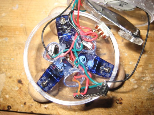 So, after the three motors are packed into the shell, the 3 ics and the array set up put on top in the to, there's not much room left over for batts - here's what the bottom half of the shell looked like after I'd packed in all those bits. I slid the three ic's into three short plastic tubes, just to keep them from bumping around a bit, and to keep the wires all in one place. In the image, I pulled one of the ICs out of it's tube, and it's propped up against the side of the shell, in the bottom of the picture

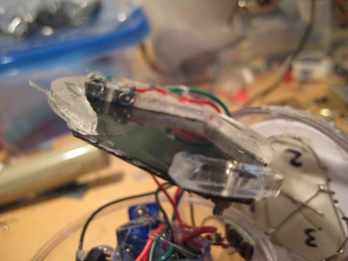
In any case, there's not much room for batts, so I used a spare skinny one from a handy cannon camera;
<------
And made a holder for it
---->
So once it's all packed, soldered togther, that's pretty much the end of the story.There's lots of improvments that could be made, such as making the motors REALLY turn at a rate that is more proportional to the different light levels between the two sensors - adding bumper switches to get it to change direction, etc. etc. I don't think it's necessary to employ a microcontroller though.
emuller.
This thing just derbys around using three differentially rotating balls to move in any direction
- Sensors / input devices: LDR
- Target environment: indoor on smooth surfaces