


The Stray
I started an new robot project which will be a long time project. The base is the 4WD chassies with 4 gear motors.
The first stage is to attach the Dagu IR compound eye on the pan tilt set in front.
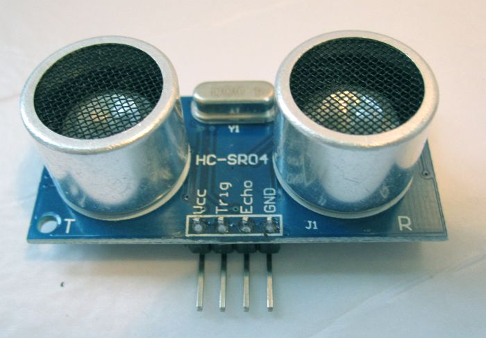
There will be one or more ultra sound sensors or infrared sensors to check the proximity.
My first choice for the brain is the Dagu Spider controller since I probably need more I/O pins than a Arduino Uno/Duemilanove can provide.
To keep in touch with the robot car I will use the mini Wi-FI router TL WR703N running OpenWRT
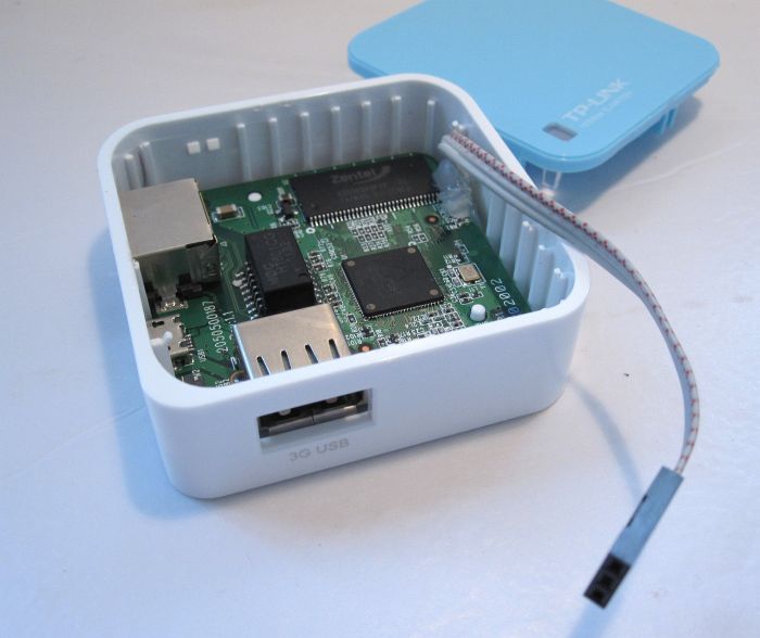
Equipped with an USB host port, an ethernet port (RJ45) I am able to attach a webcam directly to the router and send the stream to the network. The cable you see in the picture is already attached to the TX and RX pins of the router. Right now I am trying to figure out all possibilities to connect the router with the Spider controller or/and witht the network.
Also I will include a remote controlling program which will be activated and override the autonomus programming (not the self protecting behavior) as soon as the bluetooth is receiving a "go".
Additional the robot will seek light and charge the batteries when moving or resting. I am working on a solar tracker and will attach it to the chassies when done and working.
Wheel encoders, a compass module and other methods to measure his location, maybe a gripper and still not yet known things will be part of the robot with no name the name "The Stray" :-)
UPDATE Sep 10:
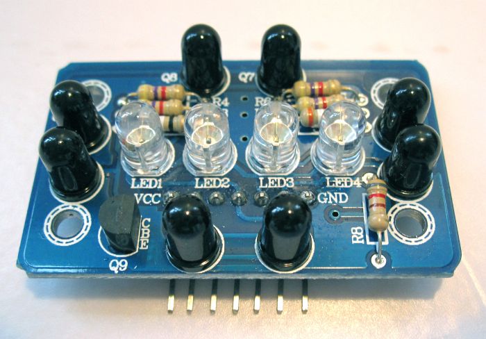
Since I was busy for weeks (Campus Party, Project ALF & Swarmbots in our local hackerspace) and also have a family the "Stray" was collecting dust. Now I reactivated it and working @ a solution for the compound eye. The first code gives me already some good output which I still have to convert to servo movement (right now it's just outputted via LED's for debugging) -> Yeah I love those LED's for debugging...even that I got two LCD's lying around :-) Code and pictures will follow.
UPDATE Sep 11:
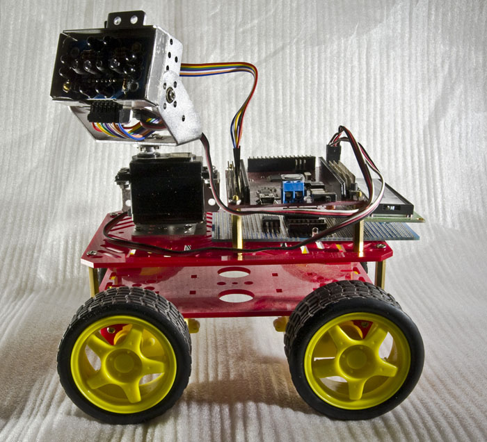
I got the compound eye is attached to the servo mount now (Note to myself: Need to find a better solution since the servo stays upright and the eye should be mounted horizontially). The code I used is this one: Arduino code for DAGU compound eye (thanks A1200, i grabbed the code and attached it to my project in case something happens with your comment there). Why invent the wheel again. This code is working for my setup just fine (maybe need to tweak that for my needs later). As the brain I used the DAGU Red Back Spider Controller, a very nice piece of a board.
The eye on the servo pan tilt mount is performing good. Movements with hand are not that stable but a piece of paper or a carton causes a very stable and smooth movement.
NOTE to the CODE: OddBot told me that the code is not complete. I will later update the file with the original code from OddBot's Mr. General.
UPDATE Oct 7:
This weekend is time to proceed with the Stray. Now my first Aluminium work on a robot. I built a case for the DAGU compound eye. As pictures says more than a thousand words, here you go...
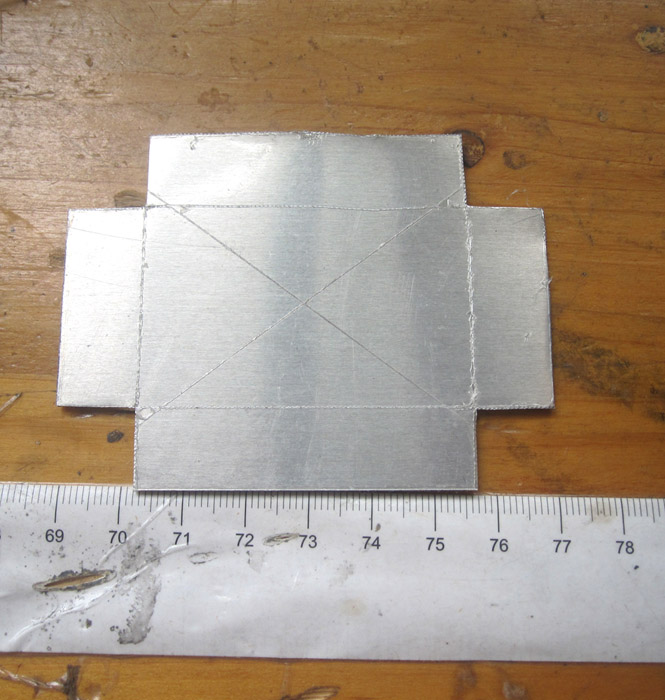
Cut from 1mm Aluminium sheet ( a bit too thick for my opinion)
Sanded the sharp edges after cutting.
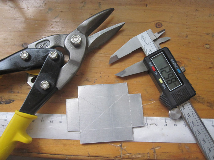
Used tools so far.
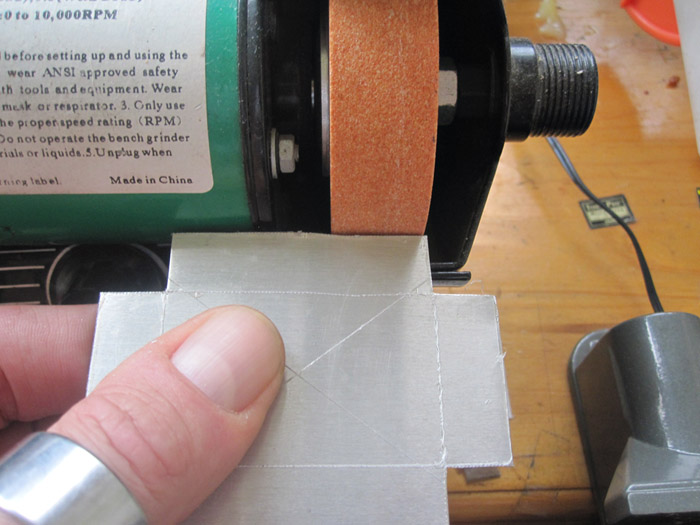
To bend the short side I used this tool. The long sides I bent with the vice (sorry, no picture)
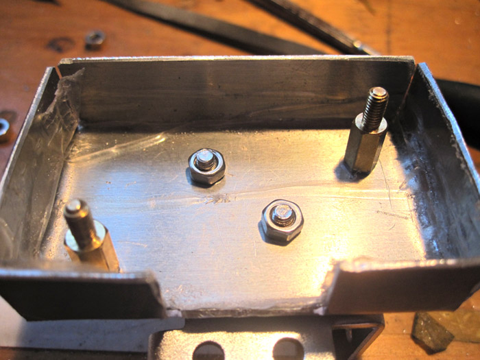
Drilled the holes with a Dremel like tool and attached the whole thing on the pan tilt mount. The standoff's are for the compound eye.
The cutout in the bottom is for the pins, as you see in the next picture.
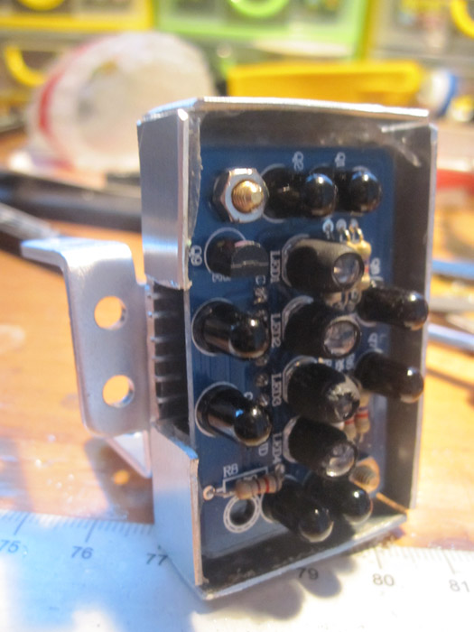
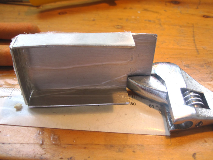
Compound eye is safe in the box now.
For my frist Aluminium work after decades I need to improve my skills. Better taking care of the bending edge since this radius has to be added when cutting the piece. Now the LED's are looking out but the plan was to keep them "inside" the case.
I kept the plastic coating on the inside for insulation reasons.
UPDATE 2 Oct 7:
Di still some soldering today. Started with the motor driver board. It will contain two L293, one for the two motors on each side, somefancy blue LED's (just to indicate that the motors are running forward), a 5V regulator L7805 and the header terminal is for a LCD with not yet decided data output.
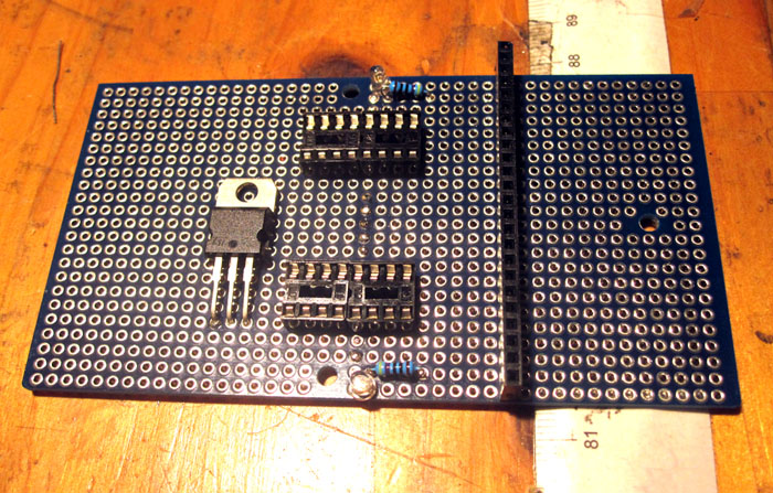
Upper side with some of the components. 2x L293, 1x L7805, 2x LED blue wth resistor, 1x header terminal for LCD.
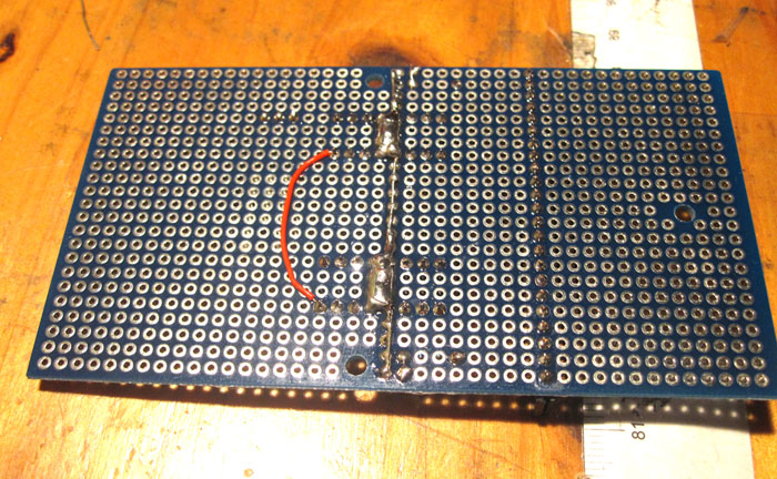
Bottom side (not that interesting as it's not finished yet).
...to be continued...
Not sure yet
- Actuators / output devices: Motors & Accessories > Gear Motors
- Control method: autonomus & bluetooth
- CPU: Arduino Mega (Spider controller)
- Operating system: Arduino IDE
- Power source: 11.1V LiPo or 5x AA + 8x AA
- Programming language: Arduino ide
- Sensors / input devices: SHARP IR sensor, compass, SRF04, IR Compound Eye, Solar panel, light sensor
- Target environment: indoors/outdoors/small areas