


The mole
Hi all,
An other robot built a few months. This one detects collisions, go backward and change direction.
Once again, no micro-controller inside... but it's the last time I swear ;) (it's more difficult and requires a lot of time for the very beginner that I am)
This time I wanted to do something more flexible. The motors are driven by PWM.
The principle
I got inspired by a french book : "Petits Robots Mobiles" by Frédéric Giamarchi (yes, him again ;)
The motors card has 4 outputs for the 2 motors and 4 inputs : 2 for speed (one for each motor) and 2 for direction (for each motor). The signal is generated by a LM 324 and the current is amplified by a ULN 2003. Then, 2 relays drive the motors.
The "brain card" has 2 outputs to send the direction of the motors. One input indicates when a colision occurs thanks to a micro-switch. It uses 2 timers (NE 555) and a resistor to adjust timing. The circuit also involves a TL 431 : when the voltage reaches a a certain threashold it lets the current go threw, this way, it lights a LED when the battery is low.
When a collision occurs (switch activation), the 2 timers get activated and init a reverse movement of a different duration for each motor (to change robot's trajectory) and then, the forward movement starts again.
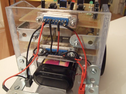
The robot uses a 7.2V battery which is regulated by a resistor, a Zener (5.6V) and a transistor to stabilize voltage.
(the ability to change the motors' speed by the "brain PCB" is not used in this robot)
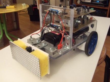
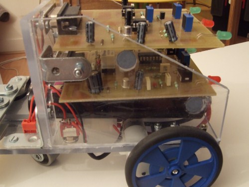
Robot's frame
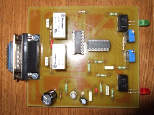
Motors' card
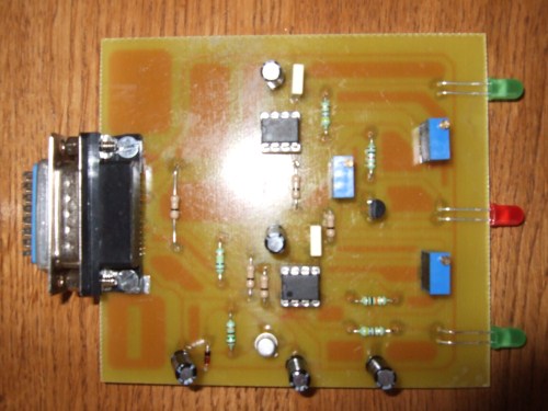
Intelligence card
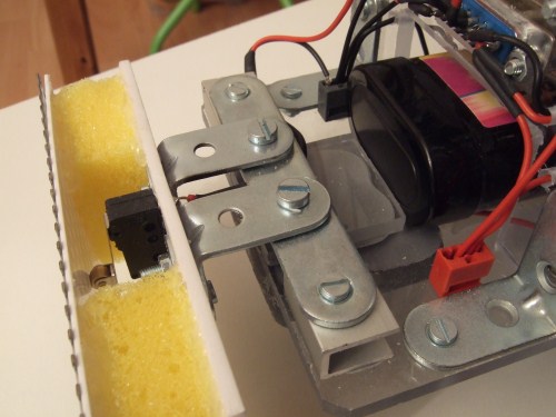
The home made collision detector ;)
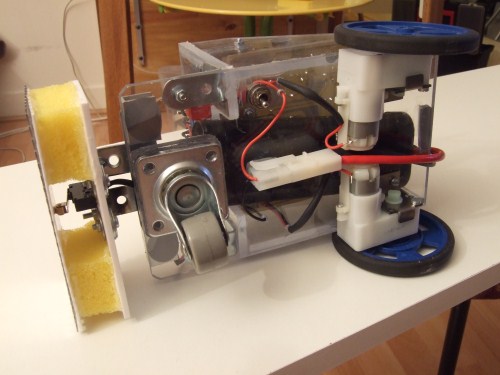

Finished robot !
I tried to power on again this robot for a video, but sadly, it doesn't work anymore as it was supposed to (it's more a bulldozer than a mole now ;)
Go backward and change direction when hitting an obstacle
- Actuators / output devices: 2 geared motors
- Control method: autonomous
- Power source: 4 AA batteries
- Sensors / input devices: bumper switch
- Target environment: indoor