


The Heavy (aka Thunderbird 2)
Since I can't drive, I need to cart goods around to conventions via train. I also need something to help me collect materials and salvage stuff.
The project started with a battered powered golf caddy I bought for £5 at a local recycling center.It was fun to play around with, but unsuitable for the above purposes. The coupling dogs from the wheels, and the axle were useful though, as was the radio control system.
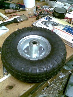
I bought some 10" hand-cart wheels off ebay, along with a pair of 180Watt golf caddy motors (geared output aprox 200rpm@12v). I already had the remains of some electric scooters laying about, and a large commercial vehicle starter battery.
My design contraints are to make something that can travel the pavements of UK cities easily, get on and off trains, take up no more space than a wheelchair or airport baggage trolly might, have as low a center of gravity as possible, and be able to fit through average household doors.
Additionally I hope to be able to use it as a mobile power supply (and avoid paying extra when trading at conventions for having a power socket at my table) as well a platform to attach other robotics project to and cargo containers.
So far I've got the design down to a footprint of 600x900mm, recessing the 10" wheels under the frame and using 7" pneumatic scooter wheels and their steering tubes as home-made castor. (off the shelf pneumatic castors seem to run to £40 or so each
The design should allow for a plentiful underslung battery bay, and both powered and manual manuverability. I'll be fitting a handlebar with manual controls at the castor (rear) end. In short it'll look like an overbuilt flatbed shopping trolly.
Bumpers should stop it from moving if it hits anything while out and about, though I hope to use the wiichuck control buttons to provide an optional override in case it needs to push something out of the way. I also intend to eventually run the system on 24v native power, but run the 12v motors via PWM at a half duty cycle. Again, an optional override to raise it to a 100% duty for emergencies (such as hurrying across a road if the lights start to change suddenly).
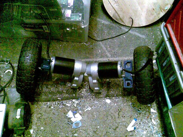
So far I've fabricated new hubs for the 10" wheels using 5mm plate steel, the steel coupling dogs from the golf caddy and silver solder. I've also got the twin axles cross-drilled for the wheel coupling bolts. Also got a set of block bearings rated for 250kg each. With 360Watts of motor power, I will be disapointed if it can't carry and move 250-300kg when complete.
Next I'll have the axles in the lathe to finish, drill and tap the ends so retaining bolts can be fitted. One to stop the wheels coming off the dogs, and at the other end to retain an optical encoder wheel on the other side of the motor. I noticed a slight difference in the output rotation speed (~15rpm) of the motors, so would like the option to compensate in software later on. Once that's done I'll be attatching them to a wooden mockup of the frame, and work on cutting the 50mm box section to make the castors. Then it's a matter of buying in steel and bribing a welder friend with drinks.
Update Jan 23rd:
Got the lathe set up and properly aligned to within about 1.5 thou. Old dial gague rather slow response so made calibrating difficult. Messed up a measurement somewhere. Cutting and finishing the axle ends took off about 3mm too much. Will have to pack with washers. Also the center drill has gone AWOL.
Also got linked to the National Rail Conditions of Carriage (pdf) which set out what's permitted or not on UK trains. I'm going to have to be careful with the length, as fitting handles to push it by will put it very close to 100cm in length. Additionally the handles will have to be under 100cm high as well. Width still won't be an issue. Page 24 of the pdf states it, but the short is if it's under those dimensions and under 50kg loaded, it should be fine to take on any train, albeit with an additional fee of up to half my ticket price again. 50-75kg, or up to 150cm in any two of the dimensions, then I'll be limited to trains with a baggage van (more rare) as well as the fee.
Good thing I was already planning for an adjustable battery bay, may need to swap out for smaller lighter batteries if I get desperate to stay within weight limits. Think I'll lean toward 1.5mm steel rather than 3mm too.
Anyway, here's a picture of the drive parts laid out very roughly on the workshop floor.
Jan 24th:
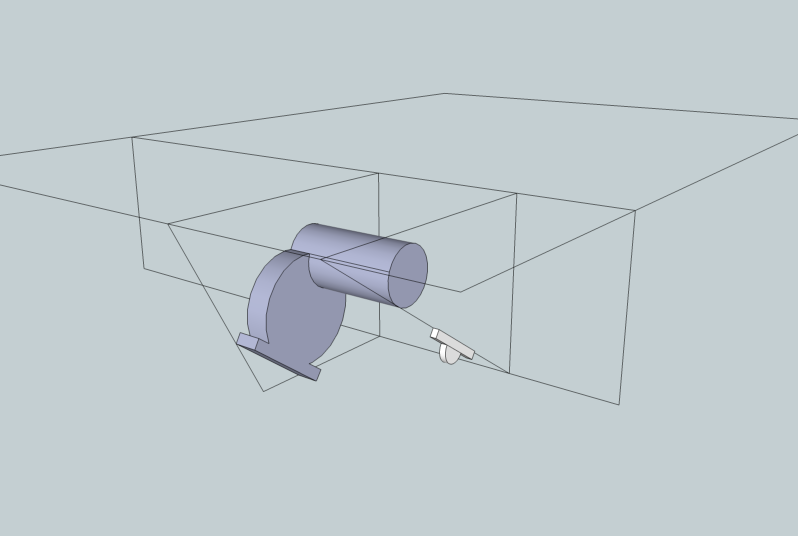
Tried my hand with Google Sketchup to make a very rough render of The Heavy. Realised may have trouble with the bearing arangement. Will have to orient the bearing block and motor the oposite way up from each other most likely.
Feb 1st:
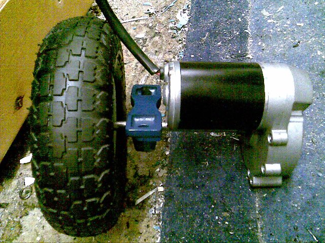
Had a terrible realisation. Realised I hadn't checked if themotor gearboxes would allow it to freewheel, or if the helixial gears would jam (I've heard some helixial gear types are far harder or impossible to turn via the output gear). Hooked the motor to the drive shaft and wheel, and it turned fine with only moderate resistance. Got both relief and a warm fuzzy feeling.
Feb 3rd:
Today I finally managed to borrow a center drill from my dad (and "Saunier's Treatise on Modern Horology", but that's a different matter).
Today is also the day the project drew first blood, with some swarf getting at my finger. Still I got the ends of one axel drilled out and tapped to M6x1.0. Next time I'll ream the bearings too, as hammering the axel into it is taking way too much force and flattens one end so it has to be filed before I can get the motor on too.
Need to dig up some split washers to help try and lock the end-bolts in place, and some M2 nylok nuts for the gearbox pin. Possibly need to thread some steel rod to make a better pin for it too. Using an M2 bolt is liable to shear since it's mild steel and threaded all the way down. Maybe if I thread a nail..?
Anyway, motor's probably going to end up turned almost onto it's side with the bearing upside down on the underside of the frame. The motor will need a dogleg. Not ideal, but it should work. Will probably go for a chain drive or something next time.
Feb 4th:
Center drilling went fine on the second axle, but my tap snapped at the last hole. Means I can get the wheel on but can't bolt anything the other side of the motor. Will have to make a new axle from scratch when I want to add theoptical encoder wheels.
For the momment though it'll do.
The cable protection gland on one motor is also smashed. I've removed it so it doesn't get into the motor. Again, it's something to replace later.
Thanks to the forum advice, next up I'll try to measure the stall current and motor resistance to correctly spec the H-bridges. And get the scooter bits ready to make the castors.
Feb 24th, 2011:
So it's been over a year since my last confession. Shit happens.
It's a short but important update. A fortnight ago I joined the local Hackspace who had a variable PSU capable of putting out 40Amps. Previous stall-current tests at home had exceeded the 20Amp range of my meters.
Stall-current tests also exceeded the range of the 40Amp supply, however measuring it at 4 different voltages that were in range gave a pretty straight-line relation between voltage and current. Using that graph I can estimate the stall current at 12v being aproximately 55 to 60Amps.
Adding a current-meter to this seems like a good idea. But at least I know the outside requirements for the H-bridges now.
Heavy load carrier and mulipurpose mobile powered base
- Control method: Wiichuck (provisional)
- CPU: Arduino
- Power source: 12v lead-acid
- Sensors / input devices: Bumpers
- Target environment: outdoor