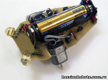
The fan of light
Всем привет ! Недавно создал статью на сайте http://rassionrobots.ucoz.ru/news/svetofil_na_batarejke/2010-07-02-176 о роботе "Светофил" и хотел бы поделиться с вами =)...
The tiny robot, is structurally executed in the form of a cockroach. Its main difference from similar robots a food of all from one battery pressure of 1,5 volts. The Robot-svetofil is capable to run behind a light source not directed on its photo cells. High light sensitivity allows the robot to run for light "зайчиком" on a floor from a lantern ray of light, that is he perceives reflected light! The minimum quantity of radio components does this robot accessible to repetition. As the power supply it is necessary to establish "a fresh" galvanic cell (battery) pressure of 1,5 volts or the charged accumulator.
As already it has been told above the robot-svetofil runs behind a light stain ahead. Therefore algorithm of movement the following. If the light stain is located approximately equally spaced from the left and right photo diode the robot runs forward. If the light stain is located more close to the left photo diode it turns to the left. If the light stain is located more close to the right photo diode светофил turns to the right.
Work principle. After food inclusion if photo diodes are not shined, the robot is motionless. Let's disassemble why it occurs. When photo diodes VD1, VD2 are not shined on base conclusions of transistors VT1, VT2 through resistors R1, R2 the positive potential arrives and closes these transistors. Accordingly on base conclusions of transistors operating the negative potential which too closes them is present motors VT3, VT4. The current through motors M1, M2 does not go, the robot is motionless. If to light, we will admit on photo diode VD1 its return resistance to decrease and on a base conclusion of transistor VT2 there will be minus a potential which will open transistor VT2. Through transition transistor VT2 emitter-collector will begin to flow a current and on a base conclusion of transistor VT4 negative potential to be replaced by the positive. Transistor VT4 will open and will connect left under the scheme motor M2 conclusion to a power supply minus. Through motor M2 the current and the robot will begin to flow will start moving. Similarly the scheme part connected with photo diode VD2 and transistors VT1, VT3 works also. If both photo diodes VD1, VD2 target transistors VT3 accordingly will open are shined, VT4 and motors M1, M2 will work simultaneously. The robot will go directly. The general sensitivity of an intensifying part of the scheme to light is that that the robot reacts to a sunlight from a window and even desk lamp light! Diodes VD3, VD4 protect transistors VT3, VT4 from an induction of motors.
In archive printed-circuit board drawings (bottom) and теромоклише. All drawings in the exact sizes. To transform and edit drawings it is impossible! After downloading unpack drawings on the laser printer. A thermocliche on a glossy paper, and the printed-circuit board drawing on usual format А4. Use a thermocliche for drawing transfer on стеклотекстолит on method ЛУТ. The printed-circuit board drawing is necessary for quality assurance of current carrying paths after lut-transfer. The password to archive: 2010
Спасибо за внимание =)
Article original: http://rassionrobots.ucoz.ru/news/svetofil_na_batarejke/2010-07-02-176


