


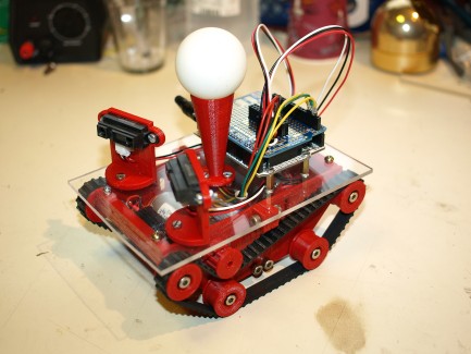
TBT (Timing Belt Tank)
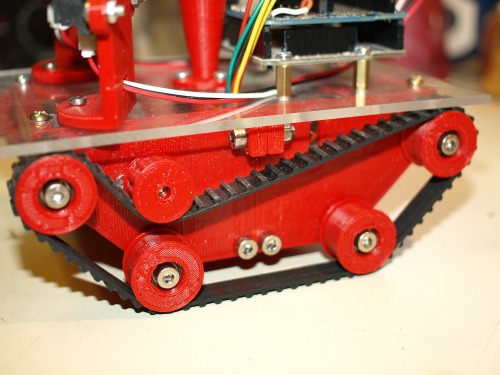
When putting the ToM (Thing-O-Matic 3D printer) together it struck me that the timing belts looks a lot like tank treads when flipped inside out. I think small robots are fun so I decided to try making a chassis based on some 140XL timing belts.
The chassis came out pretty good and for anyone wanting to print one the files are free for download at http://www.thingiverse.com/thing:8740
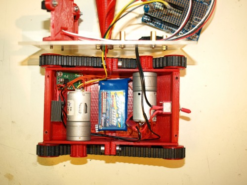
I wanted this to be a base with minimum of wiring going down to the motors, and as I had a serial motor controller from yet another unfinished project I mounted that http://www.pololu.com/catalog/product/1110 So to control the motors I would only need one wire down to the controllers and that would make it easy if I decided to change things up later on.
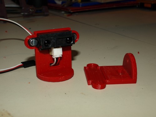
I also had two Sharp distance sensors lying around so I stuck them on in sort of crossfire configuration.
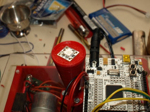
The ice cream cone, with the ping-pong ball on top houses a I2C RGB LED http://thingm.com/products/blinkm-minm.html that my brother gave to me.
The microcontroller is a FEZ Panda and probably way overkill for this little bot. The whole thing could probably be built around a PICAXE with no problems at all as you only need a serial out for motor control, a I2C for the LED and two analogue in for the sensors.
The motors are actually 12V 1000RPM running at 6V so the speed could probably be much higher but then again it seems fast enough.
The tracks
This is the holder for the RGB BlinkM. The 4 wires are inside the cone.
Some Sharp brackets
Again I would like to praise the Makerbot 3D printer http://www.makerbot.com/ and if you have the money, a ToM will give you hours of fun and open up whole new ways of making robot parts.
Navigate around using Sharp sensors
- Actuators / output devices: 12V 1000 RPM motor (run at 6V)
- Control method: autononmous
- CPU: FEZ Panda
- Operating system: NETMF
- Power source: 7, 7.4V Lipoly
- Programming language: C#
- Sensors / input devices: Sharp GP2D12
- Target environment: indoor