A 13.6KG translational drift machine
A quick build log of my 13.7KG featherweight robot "Take Cover". The robot uses a translational drift control system. This uses an accelerometer to track the rotational speed of the robot and switches the direction of the drive motors at certain points in the rotation. This means the robot can exhibit controlled motion whilst spinning at high speeds. The advantage of this is that the entire robot can be essentially a solid block. In the case of this robot, the weapon bar weighs about 8KG - more than half the weight of the robot!
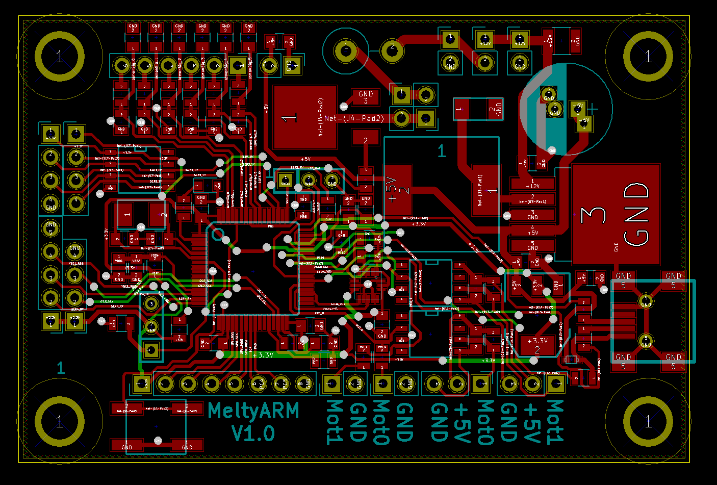
To spin at high speeds, Take Cover is fitted with two sensored 1200W skateboard motors rated at 200KV. these were used as hub motors with no gearing for a theoretical top speed of 1200rpm. These are controlled by VESC's, which are in turn controlled by a PCB of my own design hosting the translational drift controller (the same controller that was used in Nuts2 from Robot wars). A small STM32F4 PCB with high voltage DC-DC converters, CAN-BUS, opto-Isolated PPM lines, GPIO lanes for 6 channels of radio receiver, serial UART, I2C and SPI lanes. It also had a simple power switch for the high power LED used as a POV display marking the 0 point of each rotation:

The body was made of stacked lasercut 6mm nylon circles held by threading a set of 5MM machine screws up from the bottom because I have free access to a lasercutter. Cheap is best!
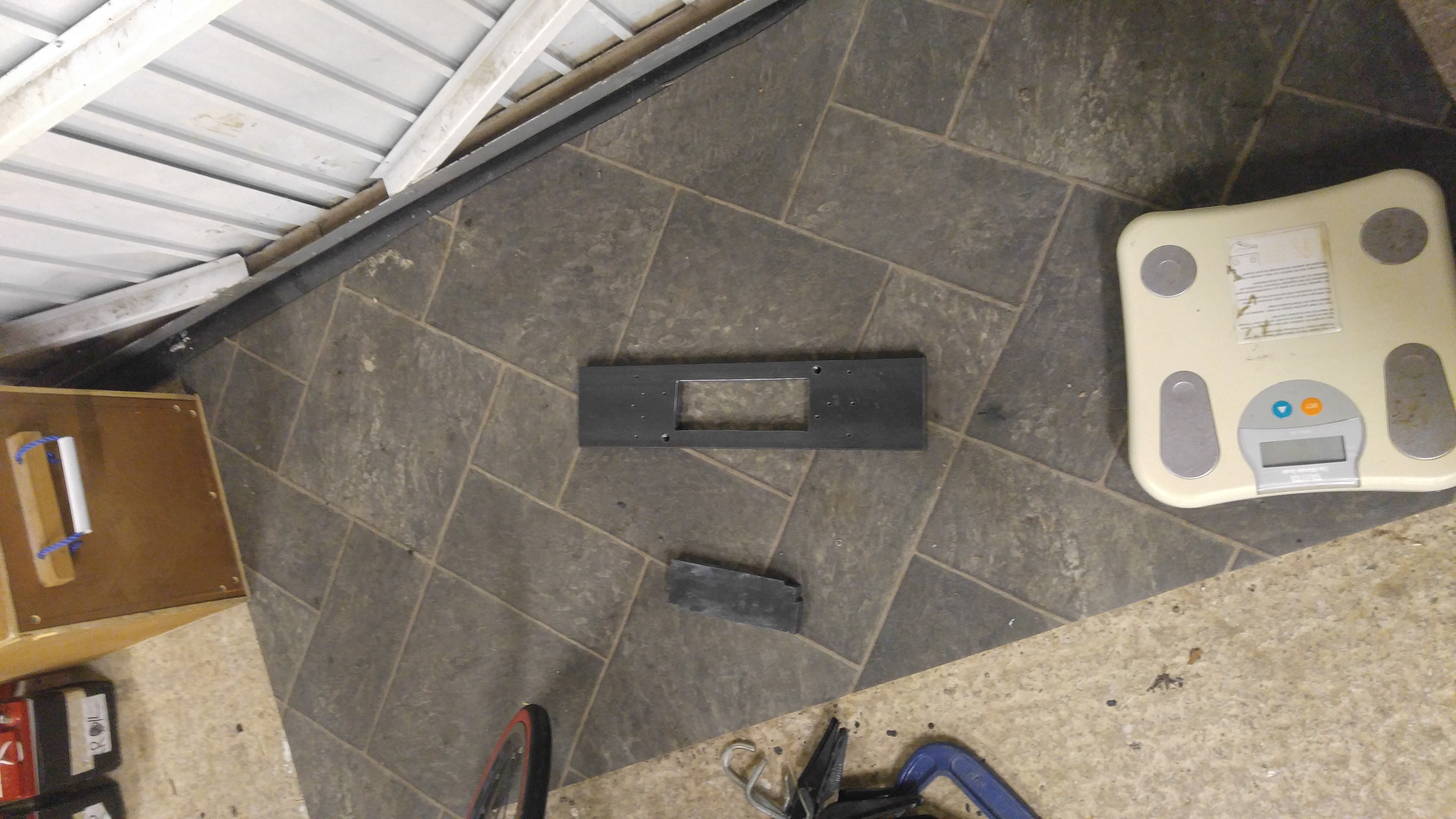
Waterjet cutting was too expensive, so here we go, cutting a 20mm mild steel weapon bar manually. Milled some small slots in the corners of the battery cutout.

This was followed by a long time with a hacksaw! Weapon balancing is overrated right?

One bar down, one more to go!

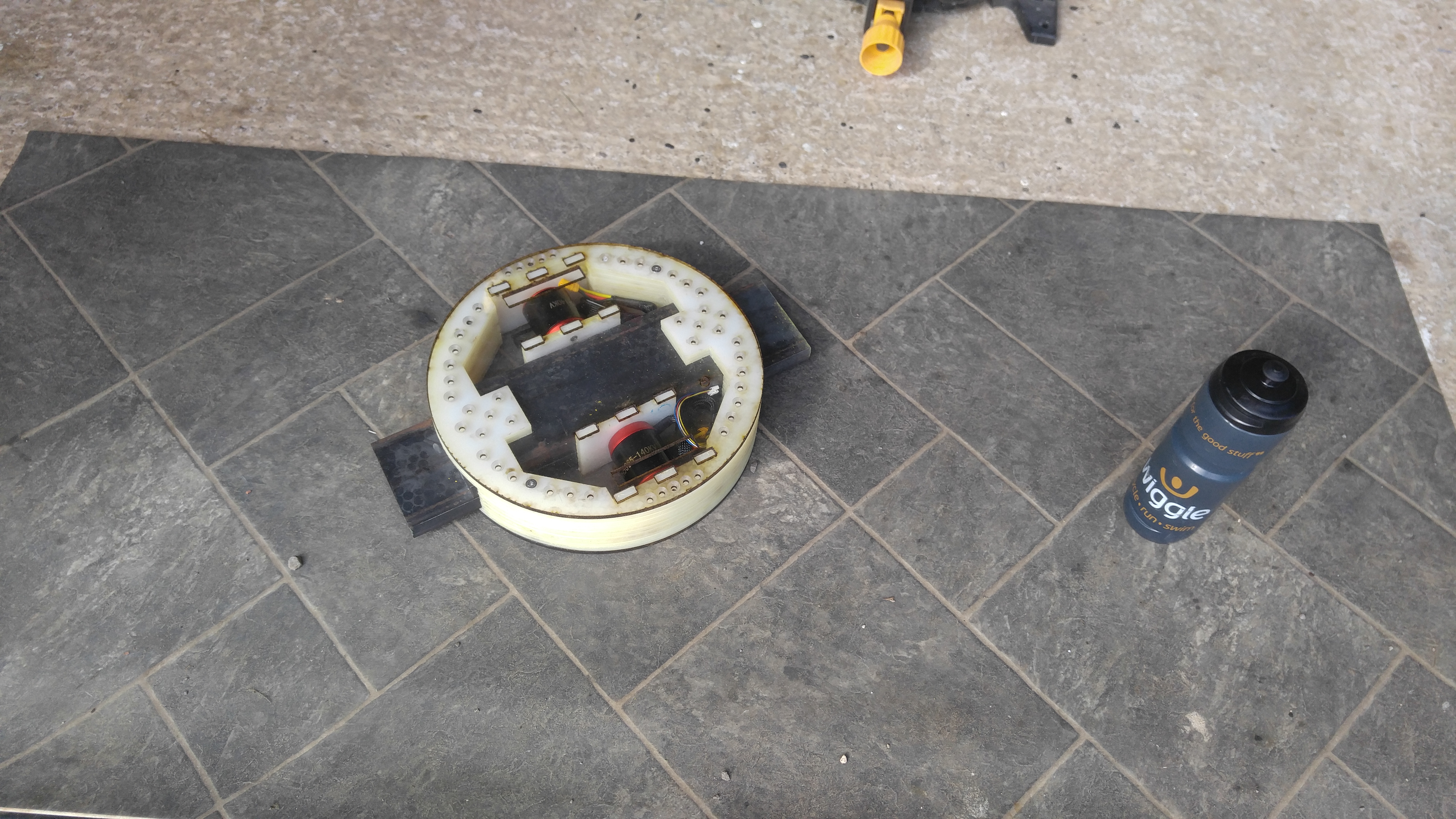
Well, here we have it, 8KG of mild steel weapon bar with the hardened steel teeth welded on and space for the battery in the middle. Only took a weekend! Sat on top of the bottom panel of the robot. This was lasered out of polycarbonate - mostly for aesthetics. These were later swapped for nylon after I found how easy an 8KG bar splits polycarbonate!

Now with the outer nylon rings, motor mounts and motors mounted:

Now with the electronics and wheels fitted.
Fun fact: the theoretical straight-line speed is over 50mph!

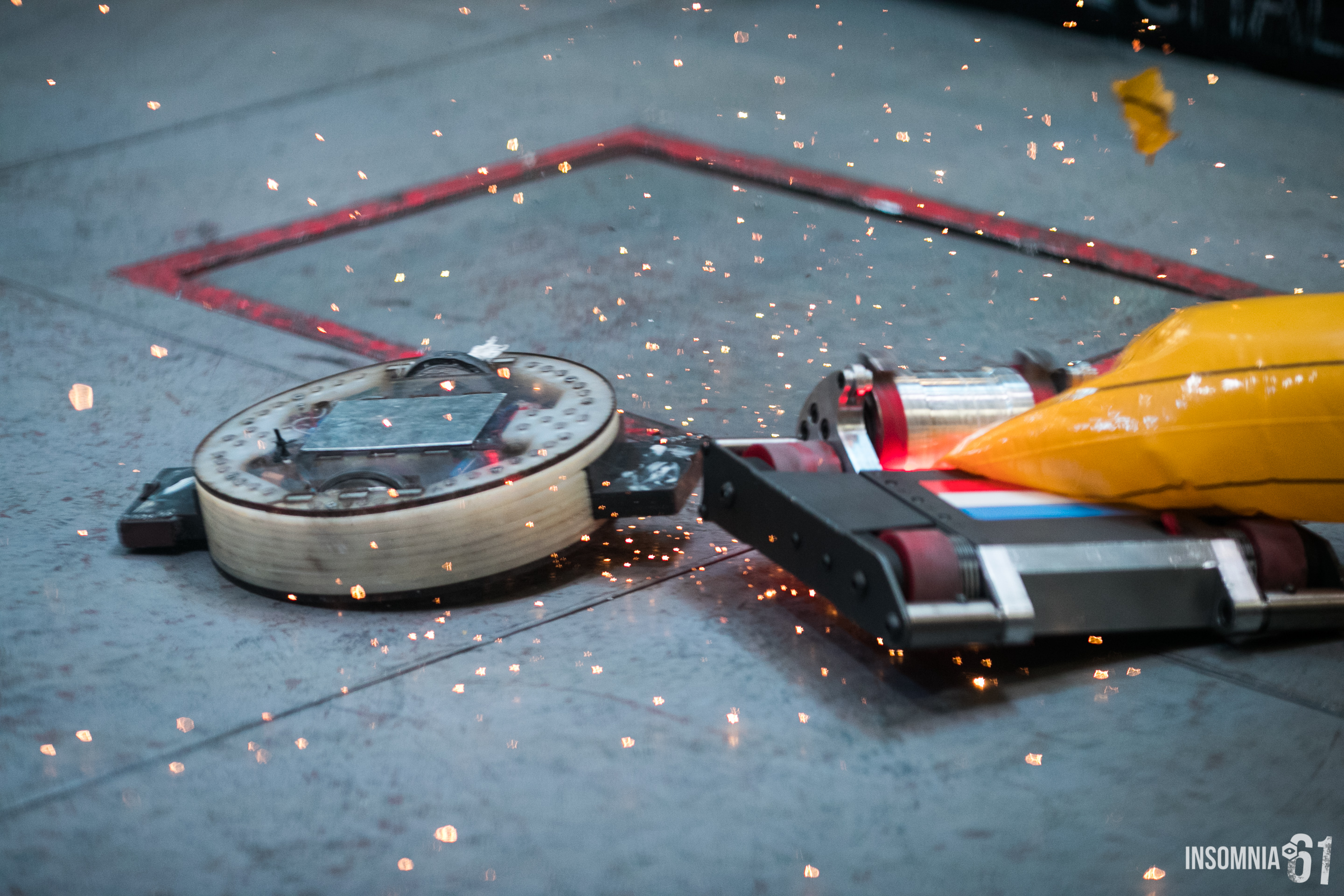
Another Fun Fact: Don't 3D print featherweight wheels from PLA. See that white fluid leaking out the top of the farthest wheel? Yeah. Just don't. Pretty sparks though!

See the full story of that banana below:
Unfortunately the molten wheel prevented the robot from turning in one direction. Of course, the translational drift system was programmed to only work in this direction, and so it was actually spinning backwards on the spot for most of this fight!
After the Insomnia 61 event, I remade those top panels from nylon, and a friend turned some replacement wheels out of aluminium. I still used the same silicon exhaust hose as tyre although it wears fast and makes a nasty mess! I also spent a lot of time tinkering with the various control systems to get it running smoothly and reliably.
Another fun fact: remember the controller PCB from earlier? Notice at the bottom left, there is a footprint for a small tactile switch that resets the MCU. After these upgrades, the robot could spin fast enough for the G-Force to depress the tiny plastic button! Took me a little while to figure out why it was resetting itself!

Returned to insomnia 63 for a second outing:
It went through one set of tyres each fight at this event, the insides on the robot were caked in shredded silicon! I was pleased with it's performance at insomnia 63 it has definitely proven it's viability as a design type, however there are improvements to be made! Main troubles are currently:
Startup torque and motor reversing: The robot can drive in two modes - a standard forward-backward turn left-turn right. This is to allow the robot to utilise its speed to use the space in the arena to escape opponents before switching into the translational drift (spinning) mode. Unfortunately, the vescs (motor controllers) in their current configuration are a bit rubbish at switching direction in a direct drive setup such as this - they are breaking the motors till standstill before applying negative torque. This makes it very hard to switch direction or control the robot in the normal driving mode. I also suspect finer control would significantly improve the translation speed. In the next version, I will be applying some of my learnings of brushless motor control from my PHD research to these controllers!
Temperature throttling: The motors get warm. Very warm. But only sometimes. I think this is an inevitable effect of using these motors as hub motors in this fashion. Both motors lost the circlips holding the outer can and magnets of the motor from slipping down the stators. This makes the gforce crush the ends of the motors against the nylon mounts as well as the aluminium wheels against the nylon top + bottom panels. This causes a lot of friction and wastes a lot of power in the motor. Next version will put a focus on motor cooling and wheel loading.
Another problem was weapon engagement. I think this is mostly due to the shape of my weapon teeth - essentially flat. This coupled with the relatively slow movement gave it a tendency to just brush off another robot instead of digging in. Think I'll try a local lasercutting company for the next version's single toothed weapon bar!
Another problem is the motor power. You might think 2400W of motors would be enough. Of course not! More power = more speed right? Who knows - but I plan to find out the fun way! More details to come in the log for the second version, but for now let's just say that on paper, the design has 1.4 times the power-weight ratio of a Bugatti Veyron! more details to follow in the build log for Version 2, codename: "The Robots Are Coming!"


